
Build-to-print components
Heavy copper PCB stators, designed for a reviewed stackup
Specify heavy copper PCB stators as winding assemblies, not just circular circuit boards. Start with the phase circuit, layer stack, installed envelope and thermal duty, then agree the fabrication and electrical acceptance route.
Engineering editorial · Reviewed 2026-10-21
The engineering decision
Define the boundary before the build.
A very thin winding can still miss its duty when conductor necks, layer transitions, hot resistance or thermal contact are left undefined. More copper and more layers also change etching, lamination, registration and dielectric requirements. Review those interactions before freezing Gerber files or quoting a board as a motor with a guaranteed output.
| Option | When it fits | Resolve before release |
|---|---|---|
| Bare PCB winding | Your team controls the rotor, mounting, cooling and motor validation. | Define circuit connectivity, terminations, finished-board geometry and electrical acceptance at the component boundary. |
| Insulated / supported stator assembly | The board needs an agreed carrier, thermal interface, protective coating or potting route. | Include the complete thickness stack, hot-state flatness, insulation and mounting condition in the release drawing. |
| Wound coreless alternative | A wound conductor and resin support may better fit the required current, envelope or revisions. | Compare resistance, connection layout, assembly effort and the actual heat path under the same duty. |
Manufacturing decision route
Review the copper, dielectric and heat path as one stack.
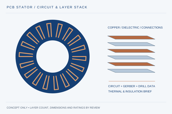
A motor winding is more than a board outline. Freeze a layer map, current convention and inspection coupon plan before the fabrication files are released. Treat each conductor transition as part of the winding circuit.
- 01
Map the winding
Identify phase paths, layer order, series/parallel connections and drill data.
- 02
Resolve the stackup
Agree finished copper, dielectric, spacing, lamination and registration requirements.
- 03
Build and inspect
Review etch/registration, connections, resistance and the agreed coupon or section.
- 04
Validate in the motor
Check back-EMF, loaded temperature and insulation in the representative rotor/cooling assembly.
| Review item | What to define | Decision it resolves |
|---|---|---|
| Copper per layer | Layer count; base versus finished copper in µm; local tolerance | Separates foil input, plated features and the conductor that sets resistance. |
| Trace and drill geometry | Line/space, minimum necks, finished holes, annular rings and interconnect current | Reviews etching and connection bottlenecks together. |
| Dielectric system | Laminate designation, dielectric thickness, Tg/CTI evidence and voltage waveform | Tg and CTI do not establish continuous winding temperature or complete insulation approval. |
| Mechanical boundary | Finished OD/ID, thickness, flatness, mounting and rotor clearance | Accounts for clamping and hot-state deformation within the axial envelope. |
| Thermal and release plan | Phase RMS current, electrical frequency, cooling contact, allowed hot spot and tests | Avoids treating copper weight alone as a current or power rating. |
For the website form, attach a PDF layer map and drawing. Arrange Gerber/drill/netlist package transfer by email after confidentiality is agreed; the form currently accepts STEP/STP/PDF, not Gerber archives.
Freeze the phase circuit before the board outline
A fabrication layer set describes shapes, but a stator review also needs the intended electrical circuit. Identify phase starts and ends, winding direction, series/parallel links and how current moves between layers. Include a netlist or an unambiguous connection drawing so fabrication and electrical inspection use the same interpretation.
Specify copper in a way the fabricator can inspect
List the copper requirement for each layer, with units and an explicit base-versus-finished convention. Then mark minimum conductor necks and connection geometry. Review whether any plating contribution applies to the feature being rated. A single copper-weight number does not define the cross-section at every current-carrying location.
Keep dielectric and mechanical clearance in the same review
The motor envelope includes dielectric, protective layers, carrier, adhesive and the installed clamping condition. Define the finished axial stack and rotor clearance instead of treating nominal board thickness as the complete air-gap boundary. Agree dielectric material and spacing with the actual drive waveform and the required insulation test.
Give heat a defined route out of the winding
Record phase current, switching and electrical frequency, duty cycle, coolant or ambient conditions, contact area and mounting pressure where relevant. Identify the allowed hot-spot location and how it will be measured. A prototype should validate its representative cooling contact; a bare-board room-temperature resistance measurement alone cannot establish continuous motor output.
Plan coupons and the motor test separately
Fabrication checks can address geometry, connectivity, resistance, copper/dielectric build and connection quality. Motor-level checks add back-EMF, loading and temperature in a specified rotor and cooling assembly. Assign each test to the party supplying that boundary and retain the fabrication revision in the result. This avoids mistaking a passed board inspection for a validated motor rating.
Send a reviewable package in stages
Before confidentiality is agreed, a non-confidential PDF can show the envelope, target layer build, quantities and unresolved questions. After an NDA is executed where needed, arrange the complete fabrication package by email. Freeze the layer map and revision together, and request separate prototype, inspection and repeat-order pricing rather than hiding engineering charges in an unexplained unit price.
Prepare your RFQ
The inputs that make a useful review.
| Input | What to send | Why it matters |
|---|---|---|
| Fabrication definition | Gerber layer set, drill data, layer map, fabrication drawing and netlist/connection definition | Makes layer order, connectivity and the finished winding boundary explicit. |
| Stackup and copper | Copper per layer in µm, base/finished convention, dielectric build and total thickness | Avoids quoting an incomplete copper-weight label without conductor or insulation details. |
| Conductor geometry | Minimum line/space, terminal necks, vias, pad/annular-ring requirements and current sharing | Identifies etching, registration and interconnect bottlenecks. |
| Operating and insulation duty | Phase RMS/peak current, waveform/frequency, bus range, cooling and voltage test requirements | Separates winding heating and insulation review from nominal system voltage. |
| Mechanical and supply brief | OD/ID, flatness, mounting/terminal details, quantities, revision and schedule | Defines the physical acceptance and prototype-to-series route. |
For confidential geometry, complete the NDA review before disclosure.
Continue your review
Related engineering programs
Questions before you specify
What layer count and copper thickness can I order?
Send the requested stackup and conductor geometry for review. Layer count, copper thickness, spacing, dielectric and total board thickness interact. The reviewed quotation identifies an accepted combination; this page does not claim a universal 26-layer or heavy-copper limit.
Can I upload Gerber files through the website?
The current form accepts STEP/STP/PDF drawings, not Gerber, drill files or ZIP archives. Attach a non-confidential PDF layer map for the initial RFQ, or use email to agree transfer of the complete fabrication package after any required NDA is signed.
Does a PCB stator remove every loss in a motor?
No. A stator without ferromagnetic teeth removes that particular tooth-cogging mechanism, but conductor loss, magnet/rotor losses, bearings and load still matter. Evaluate winding AC and DC loss and temperature under the real speed, drive waveform and cooling conditions.
Does high Tg establish the continuous motor temperature?
No. Tg characterizes a laminate transition; it is not a complete thermal-life or assembled-winding rating. Review the laminate system, insulation, adhesive, terminations, mechanical loading and qualification conditions together.
Can you supply a motor rather than just the PCB?
State whether you need a bare winding, a supported stator or a complete motor engineering program. Rotor geometry, air gap, mounting, cooling, sensing and controller responsibilities must be agreed before motor-level performance is quoted.
Further technical reading
Primary references for architecture or material context; these sources do not validate our project-specific performance.
From constraint to a controlled brief
Bring the dimensions.
Define the evidence.
Request an engineering review ↗Prototype planning target: 3–5 weeks for suitable programs after DFM, material availability and drawing freeze. Quotation confirms feasibility, cost and schedule.