
Base platform programs
Frameless disc motor kits for robotic integration
Design the motor kit around the joint’s bore, axial envelope and continuous operating duty. Agree the bearing, encoder, cooling and assembly boundary before a rotor/stator kit is released.
Engineering editorial · Reviewed 2026-10-21
The engineering decision
Define the boundary before the build.
A frameless motor is not a complete actuator. A joint’s load path, bearing stiffness, reducer if present, encoder position and heat path determine how the kit behaves in the machine. Repeated acceleration peaks and sustained holding duty also place different demands on the winding and surrounding structure.
| Option | When it fits | Resolve before release |
|---|---|---|
| Direct-drive joint | The required torque and envelope support a direct-drive assessment. | Review continuous holding torque, current and temperature rather than only peak torque. |
| Motor with a reducer | A thin motor integrates ahead of a separate reduction stage. | State motor-side and joint-side torque/speed separately. |
| Customer-built housing | The buyer controls housing, bearing and encoder integration. | Assign air-gap, mounting datums, cooling and final test responsibility. |
Integrate the complete joint stack
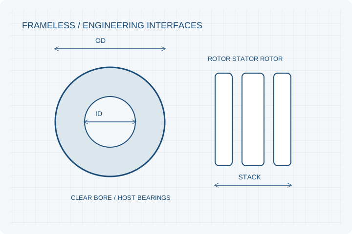
A motor kit needs the host bearings, housing and mounting stiffness to preserve its working gap. Include brake, gearbox, encoder and cable routing in the installation drawing. A motor-only thickness is insufficient when these interfaces determine the usable axial space.
Separate cogging from torque ripple
Cogging is associated with position-dependent magnetic interaction without commanded drive current; loaded torque ripple can also include winding, control and mechanical effects. Define the test configuration, load, speed and filtering for each measurement. A qualitative low-cogging description is not an acceptance limit.
Validate thermal contact in the host structure
The same frameless kit may have different continuous capability in different housings. Specify contact surfaces, interface material and surrounding temperature. Use the representative motion cycle, including stationary holding torque, when agreeing the thermal validation plan.
Prepare your RFQ
The inputs that make a useful review.
| Input | What to send | Why it matters |
|---|---|---|
| Joint envelope | OD/ID, available stack length and service routing | Ensures the bore remains usable after bearings and connectors. |
| Load and motion | Continuous/peak torque, speed, duty repetitions and holding time | Prevents a short peak from becoming an assumed continuous capability. |
| Mechanical load path | Bearing/reducer arrangement, stiffness and tolerances | Separates motor functions from structural joint loads. |
| Feedback and control | Encoder location/resolution, Hall sensing and drive interface | Defines the complete servo integration problem. |
| Thermal boundary | Housing contact, cooling and ambient/human-contact constraints | Links allowable duty to the installed heat path. |
For confidential geometry, complete the NDA review before disclosure.
Continue your review
Related engineering programs
Questions before you specify
Can you guarantee zero cogging for every kit?
No. The electromagnetic structure, manufacturing tolerance and measurement method matter. For a coreless route, tooth cogging may be absent, but total torque disturbance still needs evaluation.
Does a large bore reduce the available torque?
The bore changes active geometry and available structure. Its effect must be reviewed with outer diameter, stack length, loading and thermal limits rather than treated as a free packaging change.
Can an encoder ring be supplied?
It can be included in the integration discussion. Pole pattern, magnetic field, sensor gap, runout and sensing electronics require a separate, specific acceptance plan.
Is an axial kit always better than a radial frameless kit?
No. The right comparison is at the installed joint envelope, continuous duty, rotor inertia, cooling and total integration cost. Both approaches should be evaluated when the requirements allow them.
From constraint to a controlled brief
Bring the dimensions.
Define the evidence.
Request an engineering review ↗Prototype planning target: 3–5 weeks for suitable programs after DFM, material availability and drawing freeze. Quotation confirms feasibility, cost and schedule.