
Custom capabilities
Custom motor windings for your voltage and duty cycle
Bring your real DC-bus range, torque-speed duty and controller limits. We review winding and conductor options around the electrical system that already exists in your machine.
Engineering editorial · Reviewed 2026-10-21
The engineering decision
Define the boundary before the build.
Nominal voltage alone does not define a winding. Minimum bus voltage, maximum charged voltage, voltage utilization, phase-current limits, hot resistance and back-EMF at maximum speed all affect whether a motor can deliver the requested duty. A KV request also needs a stated measurement convention and operating condition.
| Option | When it fits | Resolve before release |
|---|---|---|
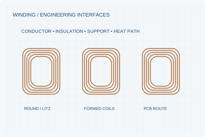
| Concentrated round-wire winding | Flexible turn-count and conductor changes are needed during prototyping. | Check fill, end-turn geometry, insulation and repeatable placement. |
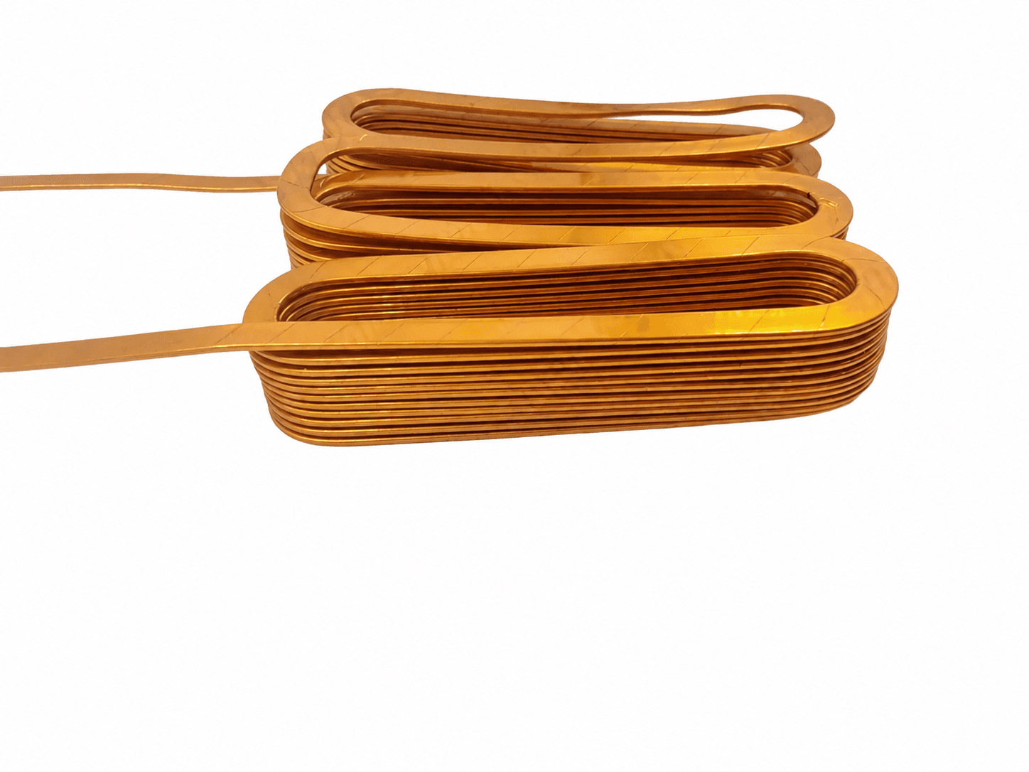
| Flat wire / formed conductors | Packaging or conductor utilization motivates a formed-wire route. | Review bend radii, joining, insulation damage and speed-dependent AC losses. |
| Litz or PCB stator route | Electrical frequency or a very flat winding structure justifies investigation. | Define frequency, current density, thermal paths and termination manufacturing. |
Begin with a torque-speed duty table
Give continuous operating points, peak duration and speed limits alongside minimum and maximum DC bus voltage. Back-EMF at speed, inverter modulation and current capability must be reviewed together. Increasing turns can change the voltage constant, but it also affects resistance, inductance and available conductor area.
Conductor choice is a manufacturing decision too
Round wire, formed rectangular conductors, Litz constructions and PCB traces have different insulation, connection and process requirements. Specify terminal access, bend constraints and impregnation needs. A conductor family alone cannot establish fill factor, efficiency or a continuous rating.
Agree the electrical test condition
Phase resistance depends on temperature, while inductance measurements depend on method and rotor position. Record test temperature, connection convention and measurement frequency where relevant. Confirm controller startup, feedback and current-ripple behavior on the motor-drive combination.
Prepare your RFQ
The inputs that make a useful review.
| Input | What to send | Why it matters |
|---|---|---|
| DC bus and inverter | Minimum/nominal/maximum bus, modulation and switching limits | A nominal 48 V or 800 V label is not a complete voltage specification. |
| Torque-speed duty | Continuous points, peak duration, repetitions and maximum speed | Separates thermal duty from a short peak request. |
| Current convention | DC input and phase RMS/peak limits stated separately | Prevents incompatible current numbers from entering the quote. |
| Winding requirements | Target KV/Ke convention, resistance, inductance and termination | Makes the electrical acceptance test reproducible. |
| Thermal and insulation | Coolant/ambient conditions, temperature sensor and insulation test plan | Links the winding to its actual cooling and electrical environment. |
For confidential geometry, complete the NDA review before disclosure.
Continue your review
Related engineering programs
Questions before you specify
Which voltages can be discussed?
24, 48, 72, 96, 400 and 800 V are useful inquiry targets. A specific design must still be checked against the complete bus range, insulation system, drive and operating duty.
Can I request a particular KV?
Yes. State whether the number is measured or estimated, the line/phase and RMS/peak convention, and the test speed. KV, torque constant and inverter utilization must be reconciled before release.
Is flat wire always the best option?
No. A higher fill factor can be offset by joining complexity, bend constraints and AC loss. The review compares a manufacturing route against the actual current, frequency and cooling duty.
Will the controller be included?
Controller matching is an optional scope. The team must agree sensor feedback, commutation, phase current, voltage margin and protection responsibilities before calling a combination compatible.
From constraint to a controlled brief
Bring the dimensions.
Define the evidence.
Request an engineering review ↗Prototype planning target: 3–5 weeks for suitable programs after DFM, material availability and drawing freeze. Quotation confirms feasibility, cost and schedule.