
Custom capabilities
Choose a cooling path that supports the real duty
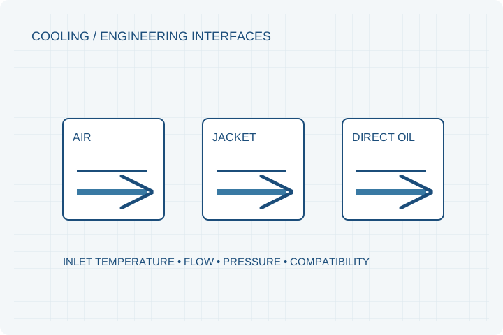
Compare air cooling, liquid jackets and direct oil cooling against the heat source, available interfaces and operating cycle. Cooling is an integration decision, not a label added after the motor is sized.
Engineering editorial · Reviewed 2026-10-21
The engineering decision
Define the boundary before the build.
A peak-power point says little about continuous operation without a defined heat path. Stator copper, core, rotor and mechanical losses reach the coolant through different interfaces. Flow available at a pump outlet is also different from flow through the installed motor, hoses and fittings. The initial review uses the complete thermal boundary.
| Option | When it fits | Resolve before release |
|---|---|---|
| Open air cooling | Airflow and environmental exposure can be controlled. | Record air temperature, velocity, ventilation path and contamination risks. |
| Housing liquid jacket | A sealed winding region and a machine-level coolant loop are preferred. | Check contact resistance, inlet temperature, flow and pressure drop. |
| Direct oil cooling | The winding or active region needs a more direct thermal interface. | Confirm fluid compatibility, drainage, sealing, churning losses and filtration. |
State the actual heat sink
Cooling descriptions need boundary conditions. For air cooling, provide airflow and ambient conditions; for a jacket, specify coolant, inlet temperature and flow. The surrounding machine may be a useful heat path, but only if the contact surfaces and interface resistance are represented in the validation fixture.
Design the wet boundary
Direct oil cooling introduces compatibility questions for wire insulation, adhesives, resin, seals and connectors. Define pressure, leakage acceptance and contamination controls. A jacket and a direct winding spray are different systems and should not share an assumed thermal rating.
Measure the duty that will be used
Run the representative load cycle until the agreed thermal condition is reached. Define winding and magnet temperature methods and the stop limits. Compare steady operation and transient peaks separately, including any coolant or fan auxiliary power in the agreed measurement boundary.
Prepare your RFQ
The inputs that make a useful review.
| Input | What to send | Why it matters |
|---|---|---|
| Continuous load cycle | Torque, speed, duration, idle/restart and peak repetitions | Identifies the thermal duty instead of averaging away overloads. |
| Coolant boundary | Fluid, inlet temperature, available flow and allowable pressure drop | Makes performance claims tied to an installation condition. |
| Temperature limits | Winding, magnet, bearing and adhesive limits plus sensor locations | The lowest component limit may govern the program. |
| Machine interfaces | Hose sizes, fittings, service access and leak requirements | Avoids a cooling solution that cannot be installed or serviced. |
| Environmental exposure | Dust, salt, oil mist and washdown conditions | Determines whether an open design is appropriate. |
For confidential geometry, complete the NDA review before disclosure.
Continue your review
Related engineering programs
Questions before you specify
Does liquid cooling guarantee a higher continuous rating?
Only if the complete heat path is effective and the fluid conditions are available in the machine. A jacket cannot compensate automatically for poor winding-to-housing thermal contact.
What information is needed for direct oil cooling?
Send the oil type, inlet temperature, flow range, filtration and drainage constraints. Material compatibility and leak boundaries must be reviewed with the winding and rotor-retention system.
Can the stator integrate cooling passages?
This is a design option rather than a universal capability claim. Passage geometry, joining, pressure testing and electrical isolation are reviewed with the selected manufacturing route.
How will the thermal result be reported?
The report should identify ambient/coolant conditions, sensors, speed, load and duration. A temperature-rise number without those conditions is not sufficient for acceptance.
From constraint to a controlled brief
Bring the dimensions.
Define the evidence.
Request an engineering review ↗Prototype planning target: 3–5 weeks for suitable programs after DFM, material availability and drawing freeze. Quotation confirms feasibility, cost and schedule.