
Build-to-print components
Build-to-print stator and rotor components
Keep your released design and define the manufacturing boundary. Compare lamination stacks, potted coreless stators and bonded rotor assemblies.
Engineering editorial · Reviewed 2026-10-21
The engineering decision
Define the boundary before the build.
Start with the non-negotiable constraints and identify what remains open to engineering recommendation. The pages below explain the information needed for review, the trade-offs to resolve and the evidence to agree before a prototype is released.
| Option | When it fits | Resolve before release |
|---|---|---|
| Axial stator laminations with a controlled stack | Turn the electromagnetic core design into a manufacturable, inspectable lamination stack. Align steel selection, cutting or stamping route, insulation and the final datum scheme before tooling. | Review inputs and acceptance criteria on the detailed program page. |
| Coreless stator winding and epoxy-potting programs | Define the coil, resin system and heat path together. Coreless stator programs begin with conductor placement and electrical acceptance, then turn those requirements into a controlled potting and inspection plan. | Review inputs and acceptance criteria on the detailed program page. |
| Rotor discs, magnet bonding and retention planning | Combine the back-iron drawing, magnet map, adhesive process and retention design into one rotor-assembly brief. Define the inspection state before committing to fixtures or a balance target. | Review inputs and acceptance criteria on the detailed program page. |
From a program direction to a reviewable brief
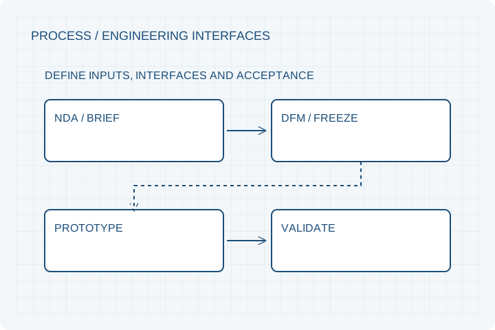
Use the specific page to collect the required dimensions, operating points and interfaces. Share sample quantity, annual volume and target schedule so the team can distinguish prototype engineering from repeat production. A 3–5 week prototype schedule is a planning target for suitable programs after DFM, material availability, drawing freeze and order confirmation; your quotation confirms the actual lead time.
Prepare your RFQ
The inputs that make a useful review.
| Input | What to send | Why it matters |
|---|---|---|
| Operating requirement | Torque or output power at speed, including peak duration | Establishes the actual duty. |
| Integration boundary | Envelope, voltage, controller and cooling conditions | Prevents interface assumptions. |
| Delivery scope | Kit, complete assembly or released build-to-print component | Assigns design and inspection responsibility. |
For confidential geometry, complete the NDA review before disclosure.
Continue your review
Related engineering programs
From constraint to a controlled brief
Bring the dimensions.
Define the evidence.
Request an engineering review ↗Prototype planning target: 3–5 weeks for suitable programs after DFM, material availability and drawing freeze. Quotation confirms feasibility, cost and schedule.