Compare turns, copper area and speed against estimated loaded voltage, copper loss and coil packing. Start with an illustrative preset, then export your inputs and results for review.
Trade coil turn count, wire gauge, and mean turn length against loaded voltage sag and stator thermal current density. Select an application preset or input custom dimensions below. All fields are required. Calculations update instantly on this device; no server or AI processing is used.
Representative Application Presets:
Current design results
Preliminary estimates only. Current density does not predict temperature or establish safe duty. AC loss and inductance need calibration; output excludes core, magnet, mechanical and no-load field losses.
!
Current-Density Screen: WARNING — Elevated current density (> 6.5 A/mm²). Review copper area, duty and cooling; this tool cannot predict temperature.
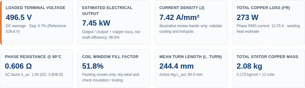
Loaded Terminal Voltage
496.5 V
DC average · Sag: 5.7% (Reference: 526.6 V)
Estimated Electrical Output
7.45 kW
Output / (output + copper loss), not shaft efficiency: 96.5%
Current Density (J)
7.42 A/mm²
Illustrative review bands only; validate cooling and hotspots
Total Copper Loss (I²R)
273 W
Phase RMS current: 12.25 A · winding heat estimate
Phase Resistance @ 80°C
0.606 Ω
AC factor k_ac: 1.00 (DC: 0.606 Ω)
Coil Window Fill Factor
51.8%
Packing screen only; dry-wind and check insulation / tooling
Your current inputs and estimates are included below. Nothing is sent until you submit the form.
How to use the coil design worksheet
Select a preset or enter the stator envelope, 4:3 pole/coil combination, turns and net copper area. All fields are required; defaults are illustrative assumptions.
Enter measured or simulated effective pole flux density and pole coverage. Magnet remanence is not the air-gap field. This tool does not solve the magnetic circuit.
Choose AC for balanced unity-power-factor line RMS current, or star/wye DC for continuous bridge output current. Adjust speed and current; results update locally and immediately.
Review sag, loss and packing warnings. Export the current worksheet and request a drawing review before choosing wire, insulation or tooling.
Calculation basis and limits
Scope: equally spaced, non-overlapping coreless coils with 4 poles per 3 coils, balanced phase assignment and equal parallel paths. Slotted stators and arbitrary winding layouts need a separate model.
No thermal certification: operating temperature is your input for resistance correction. Current-density bands (4.5, 6.5 and 10 A/mm²) and the 65% packing screen are illustrative review triggers, not universal operating limits.
Active radial length = (OD − ID) / 2. Mean turn length = 2 × radial length + 1.08 × (inner arc + outer arc). The 8% bend allowance is assumed; replace it with actual wire-path measurements during design review.
Fill = turns × bare copper area / (axial thickness × limb width). Enamel, leads, bend radii and voids are excluded. Copper mass uses 8960 kg/m³.
R20 = ρ × total phase wire length / area, with ρ = 1.7241 × 10⁻⁸ Ω·m; RT = R20 × [1 + 0.00393 × (T − 20)]. Equal parallel branches reduce resistance by the square of branch count for fixed coil count.
Frequency = pole pairs × RPM / 60. Phase EMF = √2π × frequency × series turns × winding factor × effective flux per pole. For the supported ideal 4:3 layout, winding factor = √3 / 2. Pole flux is approximated as coverage × effective field × annular area / poles; waveform harmonics are excluded.
Inductance is an isolated-loop geometry approximation, excluding mutual coupling and rotor effects. AC resistance multipliers are uncalibrated sensitivity heuristics capped at 3.5, not a bound on real losses. Compare conductor options using field analysis and supplier strand data.
AC: Vphase = max(0, √max(0, Ephase² − (Iphase X)²) − Iphase R). P = √3 × Vline × Iline at unity PF. Delta uses Iphase = Iline / √3 and excludes circulating harmonic current.
DC (star only): Vdc ≈ max(0, (3√2/π) × Eline − 2Vdiode − 2R × Idc − (3/π) × X × Idc). Line RMS current ≈ √(2/3) × Idc. This continuous-current approximation excludes capacitor-input charging, battery voltage clamping and large overlap. At zero current, the displayed average is an idealized reference, not an open-circuit capacitor voltage.
Copper loss = 3 × Iphase² × Reffective. The displayed output/(output + copper loss) ratio excludes diode, core, magnet, mechanical and other losses. It is not generator shaft efficiency. No-load magnetic-field eddy losses are also excluded.
Illustrative examples from the same model
These are input demonstrations, not tested generators or rated-power claims. Values below are calculated by the same function as the live tool. Load each preset to inspect its complete inputs and warnings.
Calculated examples · model revision 2026-11-03
Example
Speed / frequency
Voltage / output estimate
Copper loss / current density
Low-speed wind · illustrative inputs
320 RPM / 64 Hz
138.1 V DC average / 7.18 kW
1748 W / 12.87 A/mm² · CRITICAL
High-speed APU · illustrative inputs
4200 RPM / 560 Hz
423.3 V DC average / 17.78 kW
996 W / 24.32 A/mm² · CRITICAL
Micro-hydro · illustrative inputs
1200 RPM / 120 Hz
177.0 V AC line RMS / 1.16 kW
37 W / 3.65 A/mm² · LOWER
Actual worksheet execution captured 2026-11-03 using Reset to Baseline: OD/ID 280/160 mm, 16 poles/12 coils, 48 turns/coil, 1.65 mm² round copper, one branch, 8.5 × 18 mm window, effective field 0.82 T, coverage 0.72, 1500 RPM, 15 A continuous DC, 80°C, star bridge and 1.1 V/diode. Site header and floating contact control are hidden in this isolated result capture. This demonstrates software reproducibility, not a physical generator test, customer endorsement or thermal qualification.
Interpret the trade-off before choosing wire
At fixed conductor area, more turns increase both EMF and resistance. At fixed window and fill, doubling turns requires roughly half the copper area and gives about four times the DC resistance. Compare at the required voltage and power, rather than holding current constant unintentionally.
A lower current density does not establish a safe hotspot temperature. Cooling path, ambient temperature, resin conductivity, contact resistance, duty and insulation class require a thermal model and prototype measurements. Litz can reduce skin and proximity losses, but there is no universal frequency at which it becomes mandatory.
If output collapses to zero or sag becomes large, reduce current and check the electromagnetic and load models. The worksheet imposes your current demand; it does not solve a turbine torque curve, battery charging controller or self-consistent operating point.
Provide coil wire path, pole polarity and phase/polarity map, equal parallel grouping, rotor spacing and mechanical datum drawing.
Agree conductor dimensions, enamel build, bend radius and winding tension with the wire supplier; dry-wind a sample before accepting packing.
Measure cold/hot resistance, inductance, phase balance and speed–EMF; validate the rectifier with the actual load and cooling boundary.
Agree insulation tests, resin compatibility, dimensional acceptance and temperature limits for the specific program before potting. No fixed test voltage or tolerance is prescribed here.
Generator coil design questions
How does turn count affect generator loaded voltage vs open-circuit voltage?
EMF scales with turns for fixed field and speed. At fixed copper window and fill, doubling turns roughly halves conductor area and quadruples resistance. Compare voltage and power at the intended load; resistance does not scale quadratically if conductor area stays fixed.
Can I use aluminum wire in this worksheet?
No. The model uses copper resistivity, temperature coefficient and density. Aluminum needs a separate material model and a review of area, terminations and manufacturing limits.
Which winding layouts are supported?
Only an ideal equally spaced coreless 4:3 pole-to-coil layout with balanced phase assignment. Parallel branches must divide the coils per phase equally. Other layouts need winding and field analysis.
When should a generator coil use Litz wire?
When strand construction, electrical frequency and the local magnetic field make it useful. There is no universal switching frequency. The worksheet uses illustrative AC multipliers; validate loss with field analysis and supplier data.
What is the optimum inner-to-outer diameter ratio?
There is no universal optimum across clearance, thermal, magnetic and manufacturing constraints. Compare actual wire length and packing, then validate the full machine model. The tool does not optimize torque or magnet geometry.
What is a realistic coil packing fill factor?
It depends on conductor shape, enamel, serving, tooling and winding process. This tool flags fill above an illustrative 65% and rejects 100% or more. A lower fill is not a manufacturability guarantee; dry-wind and measure a sample.
Does a lower current-density result mean the coil is safe?
No. Current density does not determine hotspot temperature by itself. Cooling path, ambient, duty, resin, insulation and local field losses require thermal analysis and prototype measurements.
Does this worksheet replace FEA or solve battery charging?
No. It estimates geometry, copper loss and a simplified load envelope. DC assumes a star six-pulse bridge with continuous current, excluding capacitor-input and battery-clamped behavior. Confirm with a circuit/field model and hardware before release.
Prepare the next engineering review
Use the live result actions above to export your current design or include it in a private inquiry. Blank templates are also available: