Required setup: all fields and datum confirmation. All slot observations are required for a complete record. Results update immediately; no server request. Uniform angular spacing and a one-sided height maximum only. PASS means the entered checks passed; finished stator clearance and production release are outside this tool.
Changing coil count clears slot observations. Mid-annulus chord is illustrative; use drawing coordinates for manufacture.
Isolation selections record pass/fail against your approved procedure. No test voltage, test duration or resistance threshold is supplied by this worksheet. An insulating nest alone is not a valid test electrode.
Pitch Step Nominal
--
Mid-annulus chord: --
Recorded Checks Pass
0 / 18
Flagged: 0
Max Measured Height
--
Limit: --
Illustrative Δdiameter
--
ΔT = 0°C (Fixture vs Cu)
Setup hold items:
Drawing revision / traveler ID is required.
Primary fixture datum (Datums A, B, C) must be verified and locked.
Stator outer diameter (OD) must be a positive number.
Stator inner diameter (ID) must be a positive number.
Nominal coil axial height must be a positive number.
Maximum allowable axial height must be a positive number.
Allowable angular pitch tolerance must be a positive angle (deg).
Approved electrical test plan / record reference is required; this worksheet sets no test voltage or resistance limit.
Measured angles: 0 ≤ angle < 360° from Datum C; 359.98° is 0.02° from Slot 1 at zero. Positive heights only; no lower height limit is evaluated. Grey pending slots are not passing slots. Scroll the table horizontally on small screens.
Request DFM Review with These Fixture Datums
Share the current observation record, fixture drawing and unresolved checks for a DFM scope review. Include the approved electrical procedure and fixture revision.
Decision summary: measured evidence before irreversible encapsulation
Decision
Required evidence
When to hold
Locate from agreed datums
Drawing-defined axial plane, centering feature and angular zero; see datum concept and ASME scope [1].
Fixture registration is unknown or differs from the drawing.
Separate pitch from height
Uniform slot angle and measured peak Z; see explicit geometry method below.
Any angle exceeds the entered tolerance, or peak Z exceeds the drawing maximum.
Check thermal fit in both directions
Material-grade coefficients and actual temperature; the tool is a free-expansion illustration [2].
Binding, lost registration or unknown hot pocket clearance.
Keep electrical acceptance project-specific
Approved procedure and traceable test record; instrument guidance depends on the equipment [3].
No suitable electrode path, missing procedure or failed observation.
These are inspection planning decisions. Public sources support the method and boundaries; they do not demonstrate our fixture capability, a measured production tolerance or a qualified stator.
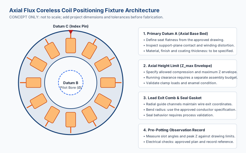
Coil fixture datum and pre-potting inspection drawing
Scroll horizontally on small screens to read all labels. Concept only, not to scale. Twelve coils illustrate the datum scheme, independent of the worksheet slot count. Add drawing-specific pocket coordinates, tolerances, sections and inspection points before fabrication.
Use A to establish the axial measurement plane, B to center the annulus and C to identify Slot 1 and the positive angular direction. A round pilot leaves angular rotation free, so the index is a separate function. Avoid redundant rigid contacts that can deform a soft winding pack. This is a concept scheme; the designer must specify the actual datum features and restraint.
ASME Y14.43 addresses fixture and gage tolerance verification. Its public scope does not supply a coil-pocket flatness, draft angle or clamp load for this application. Read ASME’s scope [1] ↗
For N equally spaced slots, the exact nominal step is 360/N degrees and Slot i is at (i−1) × 360/N. The calculation keeps full precision before comparison. It displays rounded values only for reading. Angles use the shortest circular difference, so a reading just below 360° can be close to Slot 1 at zero.
The displayed reference chord is 2r × sin(π/N), where r=(OD+ID)/4 is the mid-annulus radius. This is a geometric illustration, not the winding’s actual reference pitch circle. For OD 280 mm, ID 180 mm and N=18, r=115 mm, step=20° and reference chord≈39.939 mm. Nonuniform, skewed or layered winding coordinates require a dedicated inspection plan.
Result states and the next action
State
Meaning
Next action
INCOMPLETE / INVALID
Missing required setup or slot observations, or values outside the model range.
Complete setup and measurements; use the blank worksheet if interactive entry is unavailable.
PITCH / HEIGHT
Absolute position or upper Z limit exceeded.
Re-seat, remeasure and review the drawing limits; do not average away a high spot.
LEAD / ISOLATION
At least one recorded observation failed.
Correct routing or investigate under the approved electrical plan; the displayed badge shows one priority issue per row.
Recorded checks pass
Every entered slot passes only the evaluated checks.
Review full drawing, metrology uncertainty and process criteria before project sign-off.
Inputs accept positive geometry, 3–72 integer slots, angular tolerance below half a slot step and 0≤measured angle<360°. Temperature range −50 to 200°C is a model entry bound, not a material or process capability. The worksheet checks no lower height limit, flatness, coil width, gap between coils or 3D lead clearance.
Height screening supports a separate clearance budget
Symbolic stack, no implied air gap dimension. Rotor runout, bearing motion, thermal distortion, resin flash and measurement uncertainty need separate allowances.
Do not force an oversize coil below the height limit by tightening the fixture. Resolve the winding or seating fault and use drawing-defined hard stops and controlled contact loads. Take peak Z readings from the agreed datum and clamping condition, rather than using an average coil thickness. The upper limit must come from the approved assembly stack. A passing unpotted coil height does not establish the finished resin surface, rotor running clearance or bearing motion allowance.
No force estimate follows from this height screen. Ansys distinguishes topology and winding conventions; its note on forces on stator teeth cannot establish a rotor bearing load from displacement of a nonmagnetic coil. A topology-specific coupled model is needed for magnetic force predictions. Ansys topology scope [4] ↗
Thermal mismatch: diameter growth is not pocket clearance
The illustration uses ΔD=D × (α_fixture−α_copper) × (T_preheat−T_ambient) × 10⁻⁶. A positive value means greater free fixture diameter growth; a negative value means copper grows more. Either sign can matter. Actual radial clearance requires the local pocket dimensions and restraint; for a simple radius, free radial growth is half the diameter change.
Illustrative constant coefficients in the tool — ppm/K, not certified grade data
Material model
Coefficient
Evidence / limitation
6061 aluminum
23.0
Illustrative engineering assumption; replace with actual grade, temperature and supplier data.
P20 tool steel
12.0
Illustrative assumption; heat treatment and actual temperature range need confirmation.
Unfilled PEEK
45.0
Victrex 450G flow direction below 143°C [2]; not average isotropic expansion.
316 stainless steel
16.0
Illustrative assumption; actual stock and operating interval need confirmation.
Invar 36
1.2
Illustrative assumption; lower expansion is not automatically a closer match to copper.
Copper reference
16.5
Illustrative free-copper coefficient; insulated winding packs may behave differently.
Example: a 280 mm aluminum reference diameter heated from 22°C to 85°C gives +0.115 mm differential diameter growth using these assumed coefficients. It does not prove a 0.115 mm loose pocket. Victrex reports different coefficients by direction and temperature; the tool blocks PEEK at 143°C and above. Datasheet, page 2 [2] ↗
Lead exits: inspect the closed routing path
Distinguish a dry positioning fixture from a sealed potting cavity. Springs, sliding locators or vacuum ports used for dry handling need separation from resin or an approved sealing design before exposure to liquid resin. Check each lead from coil body through comb, cover, seal and terminal transition. A visible free lead can still be pinched when a bridge or mold half closes. Use drawing-defined bend radius and contact geometry; this page supplies no universal wire-radius, seal-compression or spring-force value.
The worksheet stores a visual alignment observation. It cannot measure a bend radius, predict leak tightness or qualify a seal. For a failed observation, reroute the lead, inspect the enamel and recheck with the intended closure configuration.
Electrical observations require an approved test plan
Record the procedure revision and measurement-record ID before marking a slot’s isolation pass/fail. The approved plan must define voltage, duration, temperature correction, electrodes, connections, discharge and acceptance. Insulation resistance, dielectric withstand and inter-turn tests are different evaluations; one is not proof of all three.
An insulating nest alone supplies no conductive return path. A high resistance reading to such a support does not establish winding insulation integrity. Have qualified personnel use the approved configuration on a de-energized assembly. AEMC’s manual explains equipment-dependent voltage selection and test precautions; it does not establish a universal pre-potting limit. AEMC manual §§1.3 and 4.3.1 [3] ↗
Resistance or waveform imbalance may justify further investigation, but this tool cannot infer turn count, circulating current, torque ripple or heating from coil angular error alone. Winding connections, speed, induced voltage and branch impedance require separate analysis.
Fixture alternatives and practical cost tradeoffs
Compare fixture approaches before requesting a quote — no price or lead-time claim
Approach
Potential fit
Cost / mismatch risk and mitigation
Dedicated machined nest
Repeatable registration for a stable geometry.
Upfront tooling and revision cost; freeze datum and pocket drawing before machining.
Adjustable prototype fixture
Geometry is still changing.
More setup and inspection labor; document each locked adjustment and recheck registration.
Combined mold and locating features
Approved tooling can both locate and encapsulate.
Limited measurement access and release risk; prove closure, access and removal on trials.
Printed sacrificial or prototype nest
Low-volume fit investigation after material review.
Creep, surface and temperature uncertainty; validate dimensions and process compatibility before use.
Hold points before resin delivery
Recheck the drawing revision and record changes after any re-seating, lead rerouting or fixture adjustment.
Risk, consequence and minimum recovery path
Risk
Consequence
Recovery / alternative
Using sample values as drawing limits
False acceptance despite incomplete design data.
Reset the example and obtain the approved tolerance stack.
Nonuniform winding forced into uniform slot model
Incorrect nominal angles and false verdicts.
Use a drawing-specific coordinate sheet and optical/CMM inspection.
A single Z reading misses a tilted coil
Local high spot can escape screening.
Map multiple prescribed points; do not treat this worksheet as a flatness inspection.
Rigid cold fit does not survive heating
Binding or loose registration at process temperature.
Review grade-specific expansion, compliance and hot dimensional trials.
Flow load inferred from injection gauge pressure
Incorrect pocket or clamp sizing.
Determine actual pressure distribution and load path in a separate process review.
Incomplete traveler exported as release
Missing or failed checks reach potting.
Use the explicit hold status and require an independent project sign-off.
Three illustrative inspection scenarios
These are constructed worksheet examples, not customer cases, shop trials or measured production results.
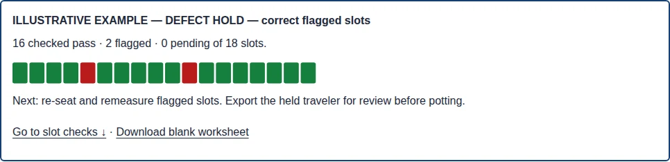
Original software execution captured on 3 November 2026 using “Try 18-coil example”: OD/ID 280/180 mm, 18 slots, ±0.15° angle limit, 5.50 mm height maximum, aluminum, 22→85°C. Slot 5 is 5.62 mm and Slot 11 has a simulated lead misalignment. This verifies worksheet behavior only; floating contact chrome is hidden in this capture. Observations are simulated, with no hardware test, customer result or production qualification implied.
1. Two defects in an 18-coil example
Assume 280/180 mm envelope, 20° uniform spacing, ±0.15° angular tolerance and 5.50 mm maximum height. The loadable example has Slot 5 at 5.62 mm and Slot 11 with a misaligned lead. With all other simulated checks entered, the tool shows 16 passing slots, 2 flagged slots and a defect hold. Re-seat Slot 5 and correct Slot 11; no production outcome is implied.
2. Valid geometry, no measurements yet
After entering a valid setup for 24 coils, blank slot fields remain pending. A 15° nominal step is a reference position, not a measurement. Exporting produces an incomplete hold record. Measure every slot and record observations before requesting release.
3. PEEK model used outside its range
If a user selects PEEK and 160°C preheat, the constant-CTE illustration is withheld. Victrex 450G data change with temperature and direction [2]. Obtain the actual fixture grade’s data and evaluate the process separately; switching the dropdown to another material does not validate a PEEK fixture.
Fixture decisions: frequently asked questions
What does this coil positioning fixture worksheet decide?
It compares recorded uniform slot angles and maximum coil heights with user-entered limits, and records lead alignment and isolation observations. It does not release a stator for production.
What are Datums A, B and C?
In the concept sketch, A is the axial seating plane, B is a centering pilot and C is the angular index. These labels must be mapped to the approved part and fixture drawing; the sketch is not a toleranced manufacturing drawing.
Is coil pitch the same as coil height?
No. Angular pitch is the separation of coil reference directions around the axis; height is the axial Z envelope from Datum A. The worksheet checks absolute angular position and an upper height limit independently.
Can I use a nonuniform or skewed winding?
The angle model assumes N equally spaced reference positions, 360/N degrees apart. For staggered layers, skew or nonuniform layouts, use a drawing-specific coordinate inspection plan instead.
Is the displayed chord my coil pitch-circle dimension?
The chord uses the mid-annulus radius (OD+ID)/4 as a geometric illustration. The actual coil reference radius may differ. Use the drawing pitch circle for manufacturing coordinates.
How are angles near zero handled?
Enter angles from zero up to but excluding 360 degrees, measured from Datum C in the drawing direction. The comparison uses the shortest angular distance: 359.98 degrees is 0.02 degrees from zero.
What height tolerance should I enter?
Enter the approved maximum Z envelope. No default manufacturing tolerance is claimed. This is a one-sided screen: low coils, flatness, tilt and finished stator thickness require separate controls.
Does thermal differential equal radial pocket clearance?
No. The displayed value is an illustrative difference in free diameter growth using constant coefficients. Radial growth is half the diameter growth. Actual clearance depends on pocket geometry, restraint and temperature distribution.
Can I use the PEEK thermal model during a hot cure?
The worksheet stops the constant-CTE PEEK model at 143°C. Victrex 450G data distinguish direction and temperature regimes. Use grade-specific data and a separate process review outside this simplified model.
Which electrical test voltage and resistance threshold apply?
Use the project-approved procedure for the specific winding insulation system and test configuration. This page prescribes no voltage or resistance threshold. Record the test-plan and measurement-record references before selecting pass or fail.
Can an insulating nest prove winding isolation?
No. An insulating support alone does not establish a conductive measurement return. The approved test plan must define electrodes, connected components and accessible surfaces; a recorded pass is not independent verification.
Do the examples represent manufactured hardware?
No. They are explicitly illustrative input and decision examples. Example data remain marked as simulated after editing. Reset the worksheet to begin a project record.
Why can I export an incomplete or defective record?
A draft traveler is useful for resolving hold items. It includes pending and defect counts, per-slot verdicts and a hold status. Export is not permission to pot or release the assembly.
Does this page specify the resin or cure schedule?
No. This page owns coil positioning, drawing datums and pre-potting inspection. Resin selection, flow simulation, cure, exotherm and final stator qualification belong in the approved potting process.
Send a reviewable fixture brief
Provide the stator and fixture STEP/drawings, winding map, datum definitions, peak-height limits, lead and terminal interfaces, process temperatures, material grades, electrical test plan and held-slot traveler. Unknown dimensions, costs and process acceptance remain pending confirmation.
Public references checked on . Only public scope or datasheet content is cited. No claim is made that paid standards were reviewed in full. Geometry equations are reproducible definitions; uncited numerical coefficients are explicitly illustrative assumptions.