
Expected N, observed −2.0 mT
Magnitude exceeds the threshold and sign opposes the drawing: REVERSED. Hold, inspect probe/face/leads and retest after an approved correction.
Find reversed or uncertain coil readings before interconnection or potting. Check signed field against your winding drawing, then export a traveler for review.
By CustomAxialFlux Engineering Editorial · Reviewed
Enter the drawing pole and measured field for each coil. Results update immediately. No winding map or measurements are assumed.
This screen compares sign and threshold only. It cannot authorize potting or establish insulation, phase sequence, torque, circulating current or thermal performance. Follow the inspection sequence.
Weak fields and missing observations stay on hold. At exactly the entered threshold, a sign can match; your procedure must already include the required uncertainty margin.
To export observations, complete the setup and correct invalid readings. Incomplete and held rows remain labeled in the CSV. The blank traveler is always available.
The request includes the drawing reference, current, threshold, observations and hold state. Correct private project details before submitting.
| Conclusion | Evidence / method | Action |
|---|---|---|
| Sign needs a reference | Current-loop direction [1] and probe-axis sensitivity [2]. | Fix face, current direction and signed probe axis before comparing. |
| A strong negative reading can be correct | Drawing S pole means −Bz under the confirmed datum; the checker compares signs. | Compare with the drawing, not with a universal North = pass rule. |
| Weak or missing data stays on hold | Instrument alignment, offset and uncertainty [2, 3]. Threshold is project-supplied. | Check setup and repeat; do not turn an uncertain value into a reversal diagnosis. |
| Insulation and release are separate | Surge comparison [4] and limited IEC scope [5] do not certify this worksheet. | Finish the agreed acceptance plan and obtain authorized release. |
Bracketed source numbers resolve in the evidence list. No hardware test records, company certification or approved current/voltage limits are supplied here.
Start and Finish are drawing conventions. Inner/outer lead position or sleeve color alone does not establish an N/S pole. Use the right-hand rule for conventional current and verify the instrument sign at the same reference face [1, 2]. A reversed observation can come from swapped leads, a flipped coil or a reversed probe; isolate the cause before changing hardware.
Coil and rotor pole counts do not uniquely determine phase order, branch wiring or expected field sign. The checker leaves those assignments to the approved winding schedule. Record actual coil serials, phase/branch positions and datum details in the traveler.
| Method | Useful observation | Limit / cost tradeoff |
|---|---|---|
| Signed Hall field at approved DC current | Direction and magnitude at one repeatable datum [2, 3]. | Needs current control, probe zero and fixture qualification; this is the checker input. |
| Referenced low-energy AC pickup | Relative phase under a validated coupling/reference arrangement. | Setup-sensitive; an ordinary RMS voltage reading alone has no directional sign. |
| Compass / transient direction check | Qualitative direction with a controlled reference. | Lower instrumentation cost; does not supply a traceable mT magnitude for this checker. |
| Continuity and 4-wire DCR | Open contacts, conductor resistance and repeatability. | Complementary only: exchanging terminal names does not change resistance. |
| Dry-connection inductance | Deviation from an approved fixture or model. | Weak coupling can hide a reversal; no universal percentage drop diagnoses it. |
| Surge waveform comparison | Differences in assembled winding response [4]. | Specialist equipment and insulation-specific procedure; not a generic low-voltage polarity step. |
Zero and orient the probe, fix its position, and document the excitation current and duration. Probe angular alignment, finite sensing area, offset and temperature affect a measurement [2, 3]. The approved threshold must separate repeatable signal from uncertainty; no fixed 1.2 mT rule applies to all stators.
For a circular air-core loop on its axis, Bz = μ₀ N I R² / (2(R² + z²)^(3/2)) [1]. As an illustrative geometry check, with R = 20 mm, moving z from 1 to 2 mm gives B(2)/B(1) = (401/404)^(3/2) ≈ 0.989, about a 1.1% reduction. This is not a field prediction for a trapezoidal coil or iron-backed stator. A universal 45% loss per millimeter is unsupported.
| Input | Website status | How to resolve |
|---|---|---|
| Expected pole and winding map | Unknown until supplied; row count supplies no winding design. | Approved drawing and current convention. |
| Current, pulse duration and thermal limit | Unknown; software accepts 0 < I ≤ 10 A only as an input range. | Coil design and approved bench procedure. |
| Field threshold and uncertainty | Unknown; demonstration values are illustrative. | Fixture trials and calibrated instrument uncertainty budget. |
| DCR, insulation and release acceptance | Not evaluated by the sign checker. | Project acceptance plan, observed measurements and authorized sign-off. |
| Step | Record / inspect | Hold or next action |
|---|---|---|
| 1. Establish identity | Drawing revision, coil serial, slot, phase/branch and expected pole. | Missing or ambiguous map: hold and ask the drawing owner. |
| 2. Confirm setup | Reference face, probe axis, current path, location, instrument/zero and approved current/duration. | Remove unintended magnetic influences; verify with the approved reference. |
| 3. Check continuity | Fixture contact and measured DCR/temperature under the agreed method. | An open observation stays on hold; de-energize before investigating contacts. |
| 4. Observe polarity | Signed Bz at the fixed datum; repeatability against the approved threshold. | Weak reading: inconclusive. Opposed sign: inspect face, leads and probe. |
| 5. Correct and retest | Approved correction, new observation and traceable recheck. | Do not simply relabel a failed coil to obtain a match. |
| 6. Check dry connections | Phase/branch continuity, terminal identity and agreed complementary tests. | Keep uncertain parallel/delta paths unconnected pending review. |
| 7. Obtain release | Completed traveler, remaining acceptance evidence and authorized quality approval. | Only the agreed approval process releases resin; this tool never does. |
Download the blank traveler. It includes blank fields for physical measurements, coil identity, inspector/time and approval. The generated CSV contains user-entered or clearly labeled example observations; neither file is evidence of a performed inspection.
If n identical, in-phase series coil EMFs each contribute e, the intended sum is ne. Reversing one changes its contribution from +e to −e, giving (n − 2)e. For n = 4 this is 2e, or half the assumed original sum. This illustrative scalar model does not determine a real distributed winding, torque, harmonics or inverter trip behavior.
For parallel branches or a delta mesh, residual EMF depends on actual phasors, branch assignments, speed and loop impedance. A standstill DC bus rating is not the back-EMF. A resistance-only ΔE/R estimate omits frequency-dependent impedance and cannot establish a safe current, temperature-rise time or risk category. This checker deliberately leaves those quantities unknown.
Megger describes surge waveform comparisons that can reveal winding differences, including reversed coils, but also other faults [4]. A waveform mismatch is not a unique diagnosis and its example thresholds are not universal acceptance limits.
The official scope of IEC 60034-15:2025 covers form-wound coils in grid-connected AC machines and excludes converter-fed windings [5]. The public scope was checked on ; paid normative test clauses were not verified. This resource supplies no surge, hipot or insulation-resistance voltage, EAR limit or cure-quality guarantee. Have the responsible engineer choose the applicable insulation procedure for the actual winding.
| Risk | Consequence / uncertainty | Mitigation or alternative |
|---|---|---|
| Probe sign or viewing face changes | False reversal or false match. | Lock the datum; re-zero and repeat the approved reference check. |
| Using illustrative values on hardware | Test heating or false acceptance; limits are unknown. | Use approved excitation and uncertainty margin, or collect a blank traveler pending review. |
| Accepting a sign match as full approval | Other winding or insulation faults remain undetected. | Keep the remaining acceptance plan and quality release separate. |
| Correcting after encapsulation | Access may be limited; resin removal can damage the winding. | Verify before encapsulation; assess accessible-lead repair against the design. No fixed scrap percentage is claimed. |
| Parallel/delta or inaccessible PCB winding | An isolated-coil field screen may not identify all interconnection errors. | Use the branch/netlist drawing and validated assembled-winding method. |
| Automating too early | Fixture cost without demonstrated discrimination. | Qualify a reference and repeatability manually before scaling to a scanner. |
These examples explain the algorithm. They are not customer tests, real stator specifications or recommended bench settings. Assume a validated datum, continuity and an illustrative threshold of 1.2 mT.
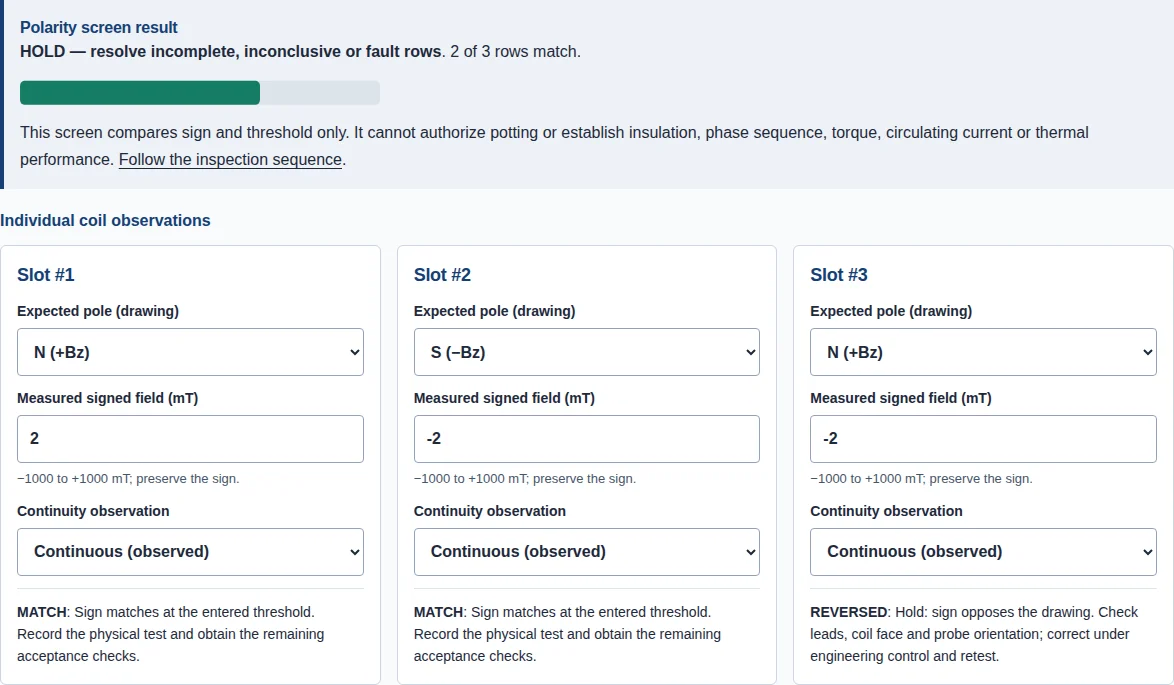
Magnitude exceeds the threshold and sign opposes the drawing: REVERSED. Hold, inspect probe/face/leads and retest after an approved correction.
Negative is the expected sign: MATCH. The sign screen is complete for this coil; remaining acceptance and release approval still apply.
Field is below threshold: INCONCLUSIVE. Verify excitation, zero and fixture position, then repeat. An open observation separately triggers HOLD_OPEN.
Supply coil geometry and conductor, winding revision, phase/branch map, lead/face conventions, test method and current/duration, instrument and fixture, uncertainty/acceptance limits, observations and encapsulation specification. Add quantities and schedule for a manufacturing review. Request an NDA before sharing confidential drawings; a request does not execute an agreement.
The tool’s review panel preserves selected inputs in the private inquiry form, email and WhatsApp brief. For a general request use the channels below.
Reviewed . Sources support the stated principles and method limitations, not a CustomAxialFlux test capability or customer-specific acceptance. The decision rule and worked examples are disclosed reasoning; actual fixture performance remains unverified.
First recorded in the repository . Source or method changes trigger a review; the next editorial review is due by 2027-04-25.
Material properties, cure quality, allowable excitation, motor output and winding repairability remain project-specific. This page owns pre-assembly polarity inspection; it does not provide a back-EMF harmonics design guide.