
Build-to-print components
SMC stator cores: from prototype geometry to production
Bring your SMC stator cores from a magnetic section drawing to a reviewable manufacturing brief. Compare an appropriate machinable sample with a powder-compacted production route before committing to tooling.
Engineering editorial · Reviewed 2026-10-21
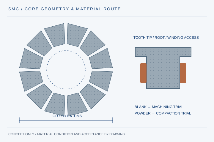
The engineering decision
Define the boundary before the build.
A three-dimensional magnetic design does not automatically become a repeatable pressed component. Tooth-tip access, thin sections, die release, local density, insulation condition and handling all affect the route. Start by stating what the first parts must prove: fit and winding access, electromagnetic performance, or a production process. Those are different acceptance questions.
| Option | When it fits | Resolve before release |
|---|---|---|
| Machinable prototype material | Early fit, winding or assembly trials where a suitable blank and machining allowance can be identified. | Confirm blank designation, available geometry, edge support and which magnetic results transfer to the intended production material. |
| Powder-compacted core | A repeat-production design with a defined powder, coating, compaction and heat-treatment route. | Review tooling access, ejection, local density, dimensional changes and qualification specimens before release. |
| Laminated electrical-steel alternative | The magnetic circuit and duty also permit a laser-cut, stacked or spiral-wound steel solution. | Compare directional flux, insulation, core loss at the actual waveform and mechanical assembly rather than assuming SMC always wins. |
Manufacturing decision route
Separate the geometry sample from the production material.
Use a machined sample to resolve the right questions, then qualify the pressed route against its own material and process conditions. A common CAD model does not make the two routes magnetically equivalent.
- 01
Freeze the section
Mark tooth tips, winding access, assembly datums and the mechanical load path.
- 02
Choose the material route
Review a machinable prototype blank or a specified powder, coating and compaction route.
- 03
Agree the inspection
Define dimensions, edge condition, density sampling and representative magnetic test pieces.
- 04
Release the next stage
Close fit and winding trials before committing to repeat-production tooling.
| Review item | What to define | Decision it resolves |
|---|---|---|
| Tooth tip and root | Minimum wall, corner radius, draft and support surfaces | Reviews press release or machining support without quietly changing the magnetic geometry. |
| Material identity | Full powder/blank designation, processing condition and supplier data revision | A 3P, 5P or 7P family name alone is not an approved core specification. |
| Magnetic duty | Flux-density waveform, electrical frequency and temperature | Defines the operating points for loss and permeability comparison. |
| Mechanical duty | Winding tension, clamping faces, assembly force and handling | Locates fragile features and distinguishes magnetic material from a structural support. |
| Release evidence | Datum-based dimensional report, material records and agreed specimens | Makes the first-article acceptance plan reproducible. |
Start with a STEP section drawing and a PDF material/acceptance brief. State whether the first parts are for fit, winding trials or electromagnetic validation.
Match the sample to the question it must answer
A fit sample can establish the installed envelope, winding-bobbin access and assembly sequence. An electromagnetic sample needs an explicitly defined material condition and representative measurements. A production trial additionally tests repeatability. Put the sample purpose on the purchase specification so a successful mechanical trial is not silently promoted into approval of production losses or torque.
Treat powder, coating and processing as one material route
SMC performance belongs to the processed component, not just the powder name. Ask for the full designation, process condition and the basis of any reference data. Do not substitute a generic furnace cycle or a catalogue test-bar value for the agreed part process. If an alternative is proposed, identify which geometry, insulation, magnetic and mechanical checks need repeating.
Review tooth geometry together with winding and support
A pole shoe that improves the magnetic section may restrict winding insertion or complicate pressing and ejection. Show bobbin splits, coil assembly direction, edge clearances and clamping faces on the same section. Support fragile features during machining and handling, then check the core again after the representative winding and potting sequence.
Make the first-article report specific
Name the drawing revision, datums, measurement state and sampling locations. For magnetic evidence, define the specimen, waveform, frequency and temperature rather than requesting an unexplained pass certificate. For density or strength, agree whether the evidence is from a process coupon or a location in the actual part; the distinction matters to acceptance.
Choose the production commitment after DFM
A prototype blank, a new pressing tool and an existing tool each create different cost and revision exposure. Request separate lines for material, fixtures, tooling, inspection and recurring parts. Confirm ownership and the cost of a geometry change before the first tool order. Lead time follows the reviewed material and validation route, not a universal promise for every SMC design.
Prepare your RFQ
The inputs that make a useful review.
| Input | What to send | Why it matters |
|---|---|---|
| Released geometry | STEP model plus PDF section drawing, OD/ID, tooth-tip/root detail, datums and tolerances | Allows a review of tool access, winding access and inspection in the final support state. |
| Material definition | Exact SMC powder or prototype blank designation; material-data revision and allowable substitutions | Somaloy 3P/5P/7P family labels do not specify the complete component process. |
| Magnetic conditions | Flux-density waveform, electrical frequency, temperature and required loss/permeability data | Makes material comparison relevant to the intended operating points. |
| Assembly conditions | Bobbin/winding layout, clamping, adhesive, potting and loads | Identifies fragile features and mechanical support responsibilities. |
| Quantity and evidence | Prototype quantity, annual volume, target schedule and first-article test plan | Separates a geometry demonstrator from a qualified production-core order. |
For confidential geometry, complete the NDA review before disclosure.
Continue your review
Related engineering programs
Questions before you specify
Can every Somaloy grade be CNC machined as a prototype?
Do not assume this. A purpose-made prototype material and a production powder-compacted grade can have different machinability and final properties. Identify the blank and its data first; agree which checks the sample is intended to support.
Can you review Somaloy 3P, 5P or 700 7P core drawings?
Include the exact material designation and current datasheet with the drawing. The review checks a suitable supply and process route; listing a family here is not a statement of stock availability or guaranteed finished-core properties. Somaloy is a Höganäs trademark; no manufacturer affiliation is implied.
Does a machined sample eliminate all NRE?
A sample route can avoid a dedicated production pressing die where a suitable blank exists. Material preparation, CAM, holding fixtures, inspection and engineering can still carry one-time charges, which should be itemized in the quotation.
Should I choose SMC or steel laminations?
Compare the required flux paths, loss at the real frequency/waveform, saturation, mechanical support, winding assembly and tooling economics. A grade name or a general high-frequency claim cannot choose the material for the whole motor.
What should I send before an NDA is signed?
Send a non-confidential section, material request and intended validation stage, or request an NDA first. The web form accepts STEP/STP/PDF; confidential detail requires an existing signed agreement and an agreed transfer route.
Further technical reading
Primary references for architecture or material context; these sources do not validate our project-specific performance.
From constraint to a controlled brief
Bring the dimensions.
Define the evidence.
Request an engineering review ↗Prototype planning target: 3–5 weeks for suitable programs after DFM, material availability and drawing freeze. Quotation confirms feasibility, cost and schedule.