
Build-to-print components
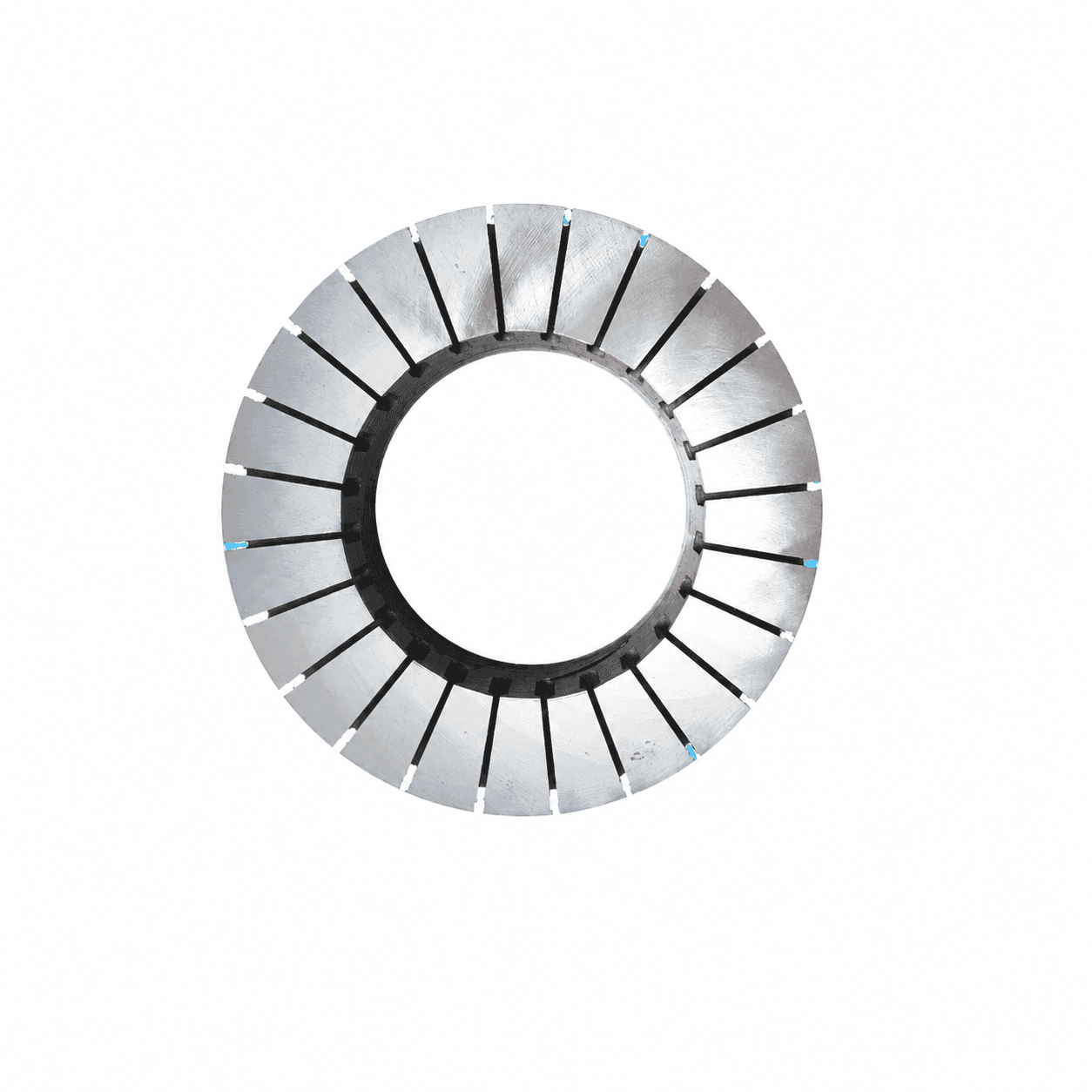
Axial stator laminations with a controlled stack
Turn the electromagnetic core design into a manufacturable, inspectable lamination stack. Align steel selection, cutting or stamping route, insulation and the final datum scheme before tooling.
Engineering editorial · Reviewed 2026-10-21
The engineering decision
Define the boundary before the build.
An axial stator drawing cannot be quoted reliably from outer diameter alone. Material thickness and loss data, grain direction where relevant, slot geometry, burr limits, stacking factor and joining method affect the finished core. A prototype route may be suitable for geometry review without representing production magnetic loss or cost.
| Option | When it fits | Resolve before release |
|---|---|---|
| Laser-cut prototype stack | Geometry is still evolving and hard-tool investment should wait. | Agree edge condition, insulation treatment and how prototype loss will be interpreted. |
| Wound / spiral core route | The core geometry and material format support a wound manufacturing route. | Review slotting, strip tension, joining and final dimensional stability. |
| Production stamping and stacking | A frozen drawing and volume plan support dedicated tooling. | Confirm tool life assumptions, burr control, insulation and stack traceability. |
Prototype route versus production route
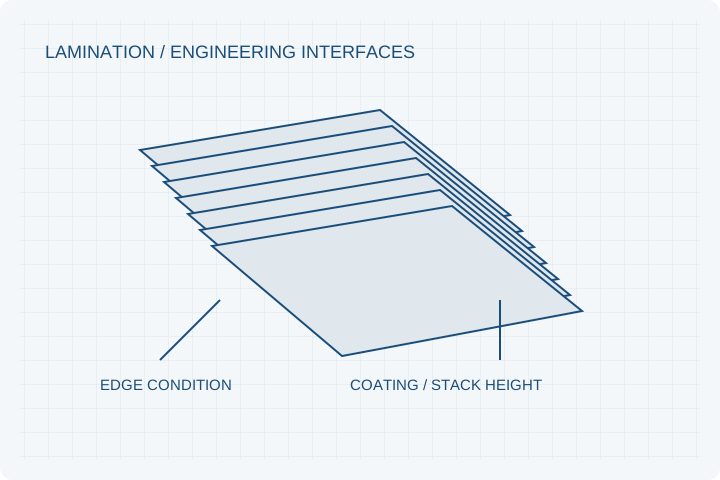
Laser-cut laminations can support early geometry evaluation without committing to a production stamping tool. Spiral or segmented stacks introduce different fixture and assembly needs. Confirm whether prototype edge condition and coating behavior are representative enough for the planned loss and temperature tests.
Specify the stack as an assembly
Steel designation, sheet thickness, coating, burr orientation and finished stack height belong in the released package. Identify whether dimensions are inspected loose, clamped, bonded or machined. The state of the stack can affect both geometric inspection and the electrical insulation boundary.
Close the first-article loop
Agree sampling locations, stack-height measurement load, datum references and any electrical or magnetic checks. Record approved material alternatives and process changes. Production tooling should follow an accepted geometry and inspection plan rather than merely reproducing an unreviewed prototype.
Prepare your RFQ
The inputs that make a useful review.
| Input | What to send | Why it matters |
|---|---|---|
| Core geometry | OD, ID, slots, tooth features and datums | Defines the actual magnetic path and inspection references. |
| Material definition | Grade, thickness, supplier data and allowed alternatives | Links simulation inputs to purchased material. |
| Stack requirements | Height, stacking factor, flatness and compression state | Prevents free-stack and clamped-stack measurements from being confused. |
| Joining and insulation | Bonding, welding or interlocking boundary plus coating | Protects electrical isolation and mechanical stability. |
| Build plan | Prototype quantities, drawing maturity and annual volume | Separates soft-route samples from production tooling economics. |
For confidential geometry, complete the NDA review before disclosure.
Continue your review
Related engineering programs
Questions before you specify
Can a laser-cut sample validate production losses?
It can help validate geometry and assembly. Cutting, edge effects, insulation and stress may differ from the production route, so loss acceptance needs a separate agreed method.
Is spiral lamination always suitable for axial stators?
No. The flux path, slot form, strip material and manufacturing sequence determine fit. We review the route against the actual electromagnetic and dimensional requirements.
Can you quote from a 3D model only?
A model is a start. A quotation still needs material, tolerances, insulation, stack state and acceptance requirements; critical notes should be on a revision-controlled drawing.
What usually changes NRE?
Drawing maturity, slot/profile complexity, tooling route, joining fixtures, inspection fixtures and volume all affect NRE. These should be separated from piece price in the quotation.
From constraint to a controlled brief
Bring the dimensions.
Define the evidence.
Request an engineering review ↗Prototype planning target: 3–5 weeks for suitable programs after DFM, material availability and drawing freeze. Quotation confirms feasibility, cost and schedule.