
Build-to-print components
Rotor discs, magnet bonding and retention planning
Combine the back-iron drawing, magnet map, adhesive process and retention design into one rotor-assembly brief. Define the inspection state before committing to fixtures or a balance target.
Engineering editorial · Reviewed 2026-10-21
The engineering decision
Define the boundary before the build.
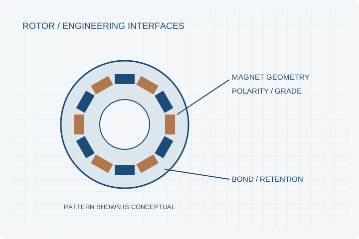
A rotor is both a magnetic circuit and a rotating structure. Machining a precise disc does not by itself control adhesive thickness, pole orientation, magnet position or hot-speed retention. The release plan needs the complete assembly, not independent certificates for unassembled parts.
| Option | When it fits | Resolve before release |
|---|---|---|
| Machined rotor disc | A released back-iron and interface drawing is available. | Specify material, heat treatment if relevant, flatness, runout and corrosion protection. |
| Bonded magnet assembly | Positioned magnets and an adhesive process are required. | Define surface preparation, bond-line controls, cure conditions and polarity checks. |
| Retention and balance program | Speed, temperature or shock needs an additional retaining structure. | Review structural responsibility, balancing configuration and an agreed overspeed plan. |
The bond-line is a controlled interface
Rotor-disc machining, magnet preparation, adhesive mixing, positioning and cure define the finished assembly. Specify bond-line thickness, surface condition and inspection access. Magnets must remain located through both manufacturing handling and the intended operating environment.
Retention and speed require a complete review
Adhesive strength alone is not a rotor-speed approval. Evaluate the retention structure, temperature, centrifugal loading and credible overspeed case. Any sleeve or mechanical feature also changes clearances and the magnetic or thermal boundary and must be reflected in the released drawing.
Balance in the defined delivery state
A bare disc, a magnetized bonded rotor and a rotor with a shaft are different balance states. Identify the shaft datum, allowable runout, balancing method and delivery configuration. Record material and process traceability with the first-article results.
Prepare your RFQ
The inputs that make a useful review.
| Input | What to send | Why it matters |
|---|---|---|
| Disc drawing | Material, datums, magnet seats, shaft interface and finish | Separates machining tolerances from magnetic-placement tolerances. |
| Magnet map | Grade, dimensions, polarity vectors and placement gaps | Prevents a visually correct but magnetically incorrect assembly. |
| Adhesive process | Preparation, bond line, cure and working temperature | Makes assembly consistency and traceability measurable. |
| Operating loads | Maximum speed, thermal cycle, vibration and shock | Defines retention assessment and test conditions. |
| Final assembly state | Installed hardware, balancing plane and allowed correction | Avoids balancing a configuration that differs from service. |
For confidential geometry, complete the NDA review before disclosure.
Continue your review
Related engineering programs
Questions before you specify
Is adhesive bonding sufficient at every speed?
No. Geometry, centrifugal loading, temperature, adhesive properties and failure consequences determine whether additional retention is needed. A project-specific structural assessment is required.
Can a carbon-fiber sleeve be added?
It can be reviewed as a retention option. Preload, thickness, material, assembly method and effects on clearance and thermal behavior must be specified, rather than assumed.
What should a balance requirement include?
The applicable standard or agreed residual-unbalance target, service speed, balancing planes, mounting fixture, final hardware and allowed correction locations should be stated.
Can the same rotor be used in a generator?
Possibly, but the speed, load, environment and thermal cycle can differ. A motor label is not sufficient evidence that a rotor meets a generator program’s duty.
From constraint to a controlled brief
Bring the dimensions.
Define the evidence.
Request an engineering review ↗Prototype planning target: 3–5 weeks for suitable programs after DFM, material availability and drawing freeze. Quotation confirms feasibility, cost and schedule.