
1. Turn shaft and load curves into rated-point inputs
The tool evaluates one operating point, not an entire turbine or load curve. Choose a speed from your measured or specified torque-speed envelope, use P = T · 2πn/60, then repeat for other points. A constant-power sweep does not represent a real prime mover unless its curve supports it.
| Input | Convention | Next verification |
|---|---|---|
| Shaft power, speed, drag | W, RPM and N·m at the same point. Friction power = drag × angular speed. | Startup torque, minimum useful charging speed and runaway overspeed are separate checks. |
| Load voltage and interface | DC bus voltage or AC line-to-line RMS voltage. | Battery charge voltage range, converter voltage/current ratings and control strategy. |
| Flux, electric loading and diameter ratio | Illustrative effective flux density, A/m sizing hypothesis and Di/Do. | Calibrate waveform and active-face conventions with FEA; verify the actual winding realizes the loading. |
| Current density and temperature | A/mm² and assumed copper temperature; not a thermal solution. | Winding fit, AC resistance, resin/insulation class, ambient and duty. |
2. Sizing equations and their limits
This worksheet retains a simplified equivalent-machine comparison equation. It is not a topology-calibrated prediction of a finished rotor envelope:
T_em = (π/8) · k_w · A · B_g · D_o³ · (1 − λ²)(1 + λ)
D_o = [8T_em / (π · k_w · A · B_g · (1 − λ²)(1 + λ))]^(1/3)
Here λ = D_i/D_o; k_w = 0.94 is assumed. D_o is in metres, A in A/m and B_g in tesla. Housing, end turns, rotor thickness and cooling structures are excluded.
Diameter ratio is a design choice, not a universal optimum
For this equation, the derivative of (1 − λ²)(1 + λ) is 1 − 2λ − 3λ², whose positive root is λ = 1/3. The often cited 1/√3 ≈ 0.58 instead follows from a different loading convention with factor λ(1 − λ²). These are different models. The preset λ = 0.58 is an illustrative starting choice; 0.55–0.65 is a comparison band, not a proven optimum or packing guarantee.
Winding and interface conventions
Assumed effective pole flux is Φ_p = 0.72 · B_g · π(D_o² − D_i²)/(8p). For balanced sinusoidal star-connected phases, E_ph = √2 · π · f_e · k_w · N_ph · Φ_p and f_e = pn/60. Turns round up to a whole number; the displayed line EMF uses those integer turns.
The 1.35 × V_LL,rms translation assumes a six-pulse bridge with continuous DC current. It does not model capacitor-input peak charging, discontinuous battery charging or controlled boost operation. A fixed 6% EMF allowance is a starting assumption; the tool flags a resistive drop exceeding that allowance. Inductive commutation drop is not solved. Direct AC output assumes unity power factor and excludes downstream converter losses.
3. Generator energy-flow and loss budget
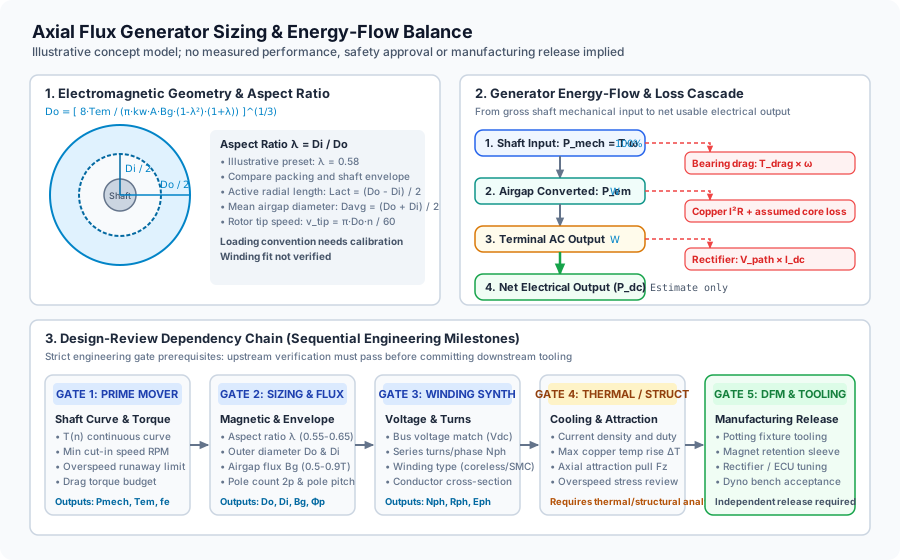
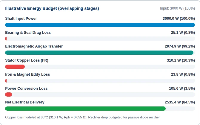
Mechanical loss is drag × angular speed without a hidden cap. Copper loss is 3I_ph²R_ph, with ρ(T) = 1.724 × 10⁻⁸[1 + 0.00393(T − 20)] Ω·m and an approximate turn length of twice the active radial leg plus 2.2 pole pitches. Phase current is an electromagnetic sizing value, not a solved load current.
Core/magnet loss coefficients are illustrative rather than material-fitted. At frequency f, they multiply airgap power by 0.008(f/50)^1.25 for coreless, 0.022(f/50)^1.1(Bg/0.8) for SMC, or 0.028(f/50)^1.3(Bg/0.8) for laminated iron. The source references do not validate these coefficients. No efficiency accuracy range is claimed.
For DC, I_dc = (P_airgap − P_copper − P_core)/(V_bus + V_path). Path-drop assumptions are 2.0 V silicon, 0.9 V Schottky, or 0.1 V synchronous rectification. Delivered power is V_bus × I_dc and rectifier loss is V_path × I_dc, so the budget balances. The synchronous drop is a placeholder, not a device rating; switching, drive and controller losses are excluded.
If friction consumes the shaft supply, or modeled electrical losses leave no positive terminal power, results and export are suppressed with a recovery action. A positive estimate still requires independent validation.
| Topology | Useful distinction | Unresolved risk |
|---|---|---|
| Coreless dual rotor | No stator-tooth cogging or stator iron loss. | Bearing drag, loaded startup torque, rotor attraction, resin heat path and magnet/back-iron eddy losses remain. |
| Laminated torus | Iron guides flux; slot/pole and lamination choices matter. | Saturation, core material loss curves, cogging and actual rotor symmetry. |
| SMC stator | Three-dimensional flux paths can be evaluated. | Use supplier loss, thermal and strength data; SMC is not automatically the lowest-loss option. |
4. Five-stage design-review dependency chain
- Prime mover: establish torque-speed envelope, startup, duty, drag and runaway RPM.
- Electromagnetic geometry: calibrate diameter/flux/loading conventions using the actual active faces and winding arrangement.
- Winding and bus matching: check coil packing, integer turns, back-EMF waveform, hot resistance, inductance and full load-line.
- Thermal and structural: validate hotspot temperatures, rotor stress, retention, disc deflection, bearing life and airgap closure. B²A/(2μ₀) is only a uniform-field pressure scale per face, not net bearing thrust. Symmetric rotors still attract one another.
- Prototype acceptance: agree CAD interfaces, tooling, insulation tests, open-circuit back-EMF, loaded dyno curves and independent overspeed qualification before production release.
The tool's 45/85 m/s, 4.8/7.5 A/mm² and 400 Hz bands organize review effort. They are illustrative screening thresholds, not adhesive strength, cooling capability or wire-loss acceptance limits.
Prepare a design review package5. Worked examples using the same calculation engine
Illustrative concepts, not delivered product ratings. Each named power is mechanical shaft input; electrical delivery is lower. Load the matching preset above to inspect every assumption.
| Concept | Shaft input | Active Do / Di / radial length | Estimated output | Frequency / tip speed |
|---|---|---|---|---|
| 3 kW Small Wind Direct-Drive Generator | 3000 W at 300 RPM | 250.3 / 145.2 / 52.6 mm | 2535 W · 84.5% · REVIEW REQUIRED | 50 Hz / 3.9 m/s |
| 5 kW Range-Extender Engine Generator | 5000 W at 2400 RPM | 124.9 / 77.4 / 23.7 mm | 4072 W · 81.4% · CAUTION | 240 Hz / 15.7 m/s |
| 1.5 kW Micro-Hydro Turbine Generator | 1500 W at 600 RPM | 158.3 / 95.0 / 31.7 mm | 1294 W · 86.2% · REVIEW REQUIRED | 80 Hz / 5.0 m/s |
| 10 kW Marine Auxiliary Alternator | 10000 W at 1500 RPM | 179.2 / 107.5 / 35.8 mm | 7786 W · 77.9% · CAUTION | 200 Hz / 14.1 m/s |
6. Alternator, rectifier and controller choices
A permanent-magnet alternator produces variable-frequency AC. Its back-EMF generally rises with speed. A passive bridge does not regulate voltage, an active synchronous bridge does not automatically provide boost or zero-voltage switching, and grid connection needs a converter with the appropriate synchronization and protection. Compare converter operating range against minimum speed, rated load and open-circuit overspeed voltage.
MPPT can improve turbine/load matching only within the controller's actual ratings and control envelope. It does not guarantee startup, prevent every stall or replace dump-load and overspeed protection.
7. Boundary conditions and failure modes
- Airgap closure: rotor-to-rotor attraction can deflect discs even when net external axial force is balanced. Assess assembly, tolerance and transient loads.
- Magnet retention: calculate centrifugal and thermal stresses at maximum overspeed. Rated tip speed alone cannot qualify adhesive or a retaining ring.
- Demagnetization: check the chosen supplier's temperature-dependent B-H curves and worst-case fault field. No universal magnet-grade temperature threshold applies.
- AC winding loss: strand size, proximity field, waveform and frequency govern AC resistance. Selecting Litz in this worksheet does not reduce the DC-only copper loss model.
- Curve mismatch: a usable rated point does not prove low-speed charging, stable load control or 50/60 Hz grid compatibility.
8. Continue with the appropriate engineering resource
9. Frequently asked questions
What is the primary sizing equation for an axial flux generator?
This worksheet uses the simplified equivalent-machine scaling Tem = (π / 8) * kw * A * Bg * Do^3 * (1 - λ^2)(1 + λ). It compares active diameters under assumed flux, winding and loading conventions. It is not a universal topology-calibrated sizing law, finished housing dimension or validated hardware rating.
Is the diameter ratio 0.58 always optimal?
No. The factor (1 - λ^2)(1 + λ) used here peaks at λ = 1/3. The value 1/√3 ≈ 0.58 comes from a different loading convention with factor λ(1 - λ^2). Our 0.58 preset is illustrative; winding packing, shaft space, active-face count and thermal constraints need project-specific optimization.
How does an axial flux generator differ from an axial flux alternator?
In technical literature, 'generator' and 'alternator' are often used interchangeably for permanent magnet synchronous machines. Strictly speaking, an alternator produces alternating current (AC) at its stator phase terminals. When integrated with a 6-pulse diode bridge, low-drop Schottky rectifier, or active synchronous MOSFET stage to feed a battery bank or DC bus, it functions as a DC generator system.
Can I use analytical equations instead of 3D FEA simulation software?
Use this worksheet for concept comparison only. No dimension or efficiency accuracy range is established. Calibrate electromagnetic conventions, material losses and winding fit with suitable FEA, then validate the thermal and structural design and prototype load curves.
What role does an Electronic Control Unit (ECU) play in generator design?
A suitable controller may match variable-speed generation to a bus within its voltage, current and control envelope. A synchronous rectifier alone does not guarantee boost, MPPT, startup or overvoltage protection. Verify the actual converter topology and protection functions.
What causes the high axial magnetic attraction force in slotted machines?
B²A/(2μ0) gives a uniform-field magnetic pressure scale per face, not net bearing thrust. Rotor symmetry may balance external forces while large internal attraction and disc deflection remain, including in coreless dual-rotor assemblies. Verify the actual field and structural load path; no residual thrust percentage is assumed.
10. Prepare the RFQ and independent review
Provide the torque-speed curve, minimum/rated/maximum RPM, electrical bus range and load curve, converter details, installation envelope, shaft and bearing interfaces, ambient/cooling/duty, selected materials and required deliverables. Include model assumptions and unresolved warnings with the exported brief.
Use the result-specific email or drawing submission form above to retain the selected parameters. A submitted worksheet requests review; it does not establish manufacturing approval.
Sources and model evidence
Reviewed 2026-11-06. These references support modeling conventions and verification methods; they do not validate this worksheet's coefficients, dimensions, efficiency or hardware safety. The loading-convention discussion is also informed by the ideal-machine derivation in Parviainen's dissertation, Chapter 1.
CustomAxialFlux engineering editorial reviews this resource at least every six months and whenever its model, input conventions or supporting references change. The next scheduled review is 2027-05-06; corrections trigger an earlier review.
- Ansys Motor-CAD: Axial Flux Machine Topologies
Rotor-stator arrangements and per-winding current, back-EMF and loss reporting conventions, especially the Double Windings section. Does not establish back-EMF scaling. Checked 2026-11-06.
- Ansys Maxwell: Defining an Axial Flux Brushless DC Motor
Geometry and winding setup for a machine model; does not validate this worksheet's sizing coefficients or ratio optimum. Checked 2026-11-06.
- Texas Instruments TIDA-010031: High-speed sensorless BLDC motor drive
TIDUEJ4, section 2.2 (printed page 3): low-inductance motor commutation and back-EMF detection context. This motoring inverter reference does not validate generator rectification, boost, MPPT or custom winding compatibility. Checked 2026-11-06.
- Parviainen: Design of Axial-Flux Permanent-Magnet Low-Speed Machines (2005), Chapter 1
Ideal-machine diameter-ratio derivation under a different loading convention; not a validation of the worksheet model. Checked 2026-11-06.