
Base platform programs
Coreless axial generators for low-speed energy systems
Define the speed range, mechanical torque and electrical load before choosing a disc-generator configuration. Wind, micro-hydro and range-extender programs have different operating and starting conditions.
Engineering editorial · Reviewed 2026-10-21
The engineering decision
Define the boundary before the build.
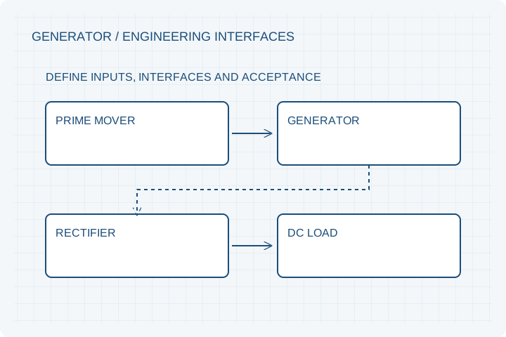
A low-RPM generator is not specified by watts alone. The available shaft torque, rectifier and DC load determine where the machine operates. Open-circuit voltage is not loaded output, and eliminating tooth cogging does not eliminate bearing, seal, load or other starting resistance.
| Option | When it fits | Resolve before release |
|---|---|---|
| Wind direct-drive program | A turbine torque-speed curve is available or being developed. | Separate aerodynamic cut-in, mechanical starting torque and electrical loading. |
| Engine range extender | A governed speed range and required DC output are known. | Review engine torque, rectification, controller strategy and thermal duty. |
| Generator active parts | The customer integrates the stator and rotor into its own machine. | Assign bearings, air-gap control, housing and final-system testing. |
Voltage must be checked under load
Open-circuit back-EMF helps describe the winding, but useful output depends on resistance, rectification and the downstream load. Specify electrical output at several speeds, battery voltage range and controller behavior. The load circuit determines whether a voltage threshold results in meaningful charging current.
Low speed requires shaft torque
At 100 RPM, 1 kW of mechanical shaft power requires about 95.5 Nm before generator and rectifier losses. This is a sizing example, not a catalog performance claim. Provide the prime-mover torque curve to establish whether the desired operating points are available.
Define startup and overspeed separately
No-load starting resistance, loaded generation torque and maximum credible speed are distinct requirements. Coreless construction does not remove bearing or seal friction. Include the protection strategy and agreed rotor retention boundary in the review.
Prepare your RFQ
The inputs that make a useful review.
| Input | What to send | Why it matters |
|---|---|---|
| Mechanical input | Speed range and available torque-speed curve | Sets an actual energy input boundary. |
| Electrical output | AC/DC requirement, load voltage and rectifier/controller arrangement | Distinguishes open-circuit and loaded performance. |
| Starting requirement | Maximum allowed torque and test configuration | Avoids claiming zero starting resistance from a coreless label. |
| Environment | Ambient, cooling, moisture, salt and mounting orientation | Drives resin, sealing, corrosion and support decisions. |
| Acceptance points | Speed, load, temperature and continuous duration | Makes a generator output curve comparable and reproducible. |
For confidential geometry, complete the NDA review before disclosure.
Continue your review
Related engineering programs
Questions before you specify
Can a low-RPM generator produce high power without high torque?
Mechanical power still follows P = Tω. For example, 1 kW mechanical input at 100 rpm requires about 95.5 Nm before losses. Low speed does not remove that torque requirement.
Does vertical-axis wind mean axial-flux generation?
No. Vertical axis describes the turbine shaft orientation. Axial flux describes the electromagnetic geometry of the generator; the two choices are separate.
Can the generator connect directly to a battery?
Not as a universal assumption. Rectification, voltage limits, load control, protection and the turbine/engine operating curve must be reviewed as a system.
Is the available catalog photograph an offered rating?
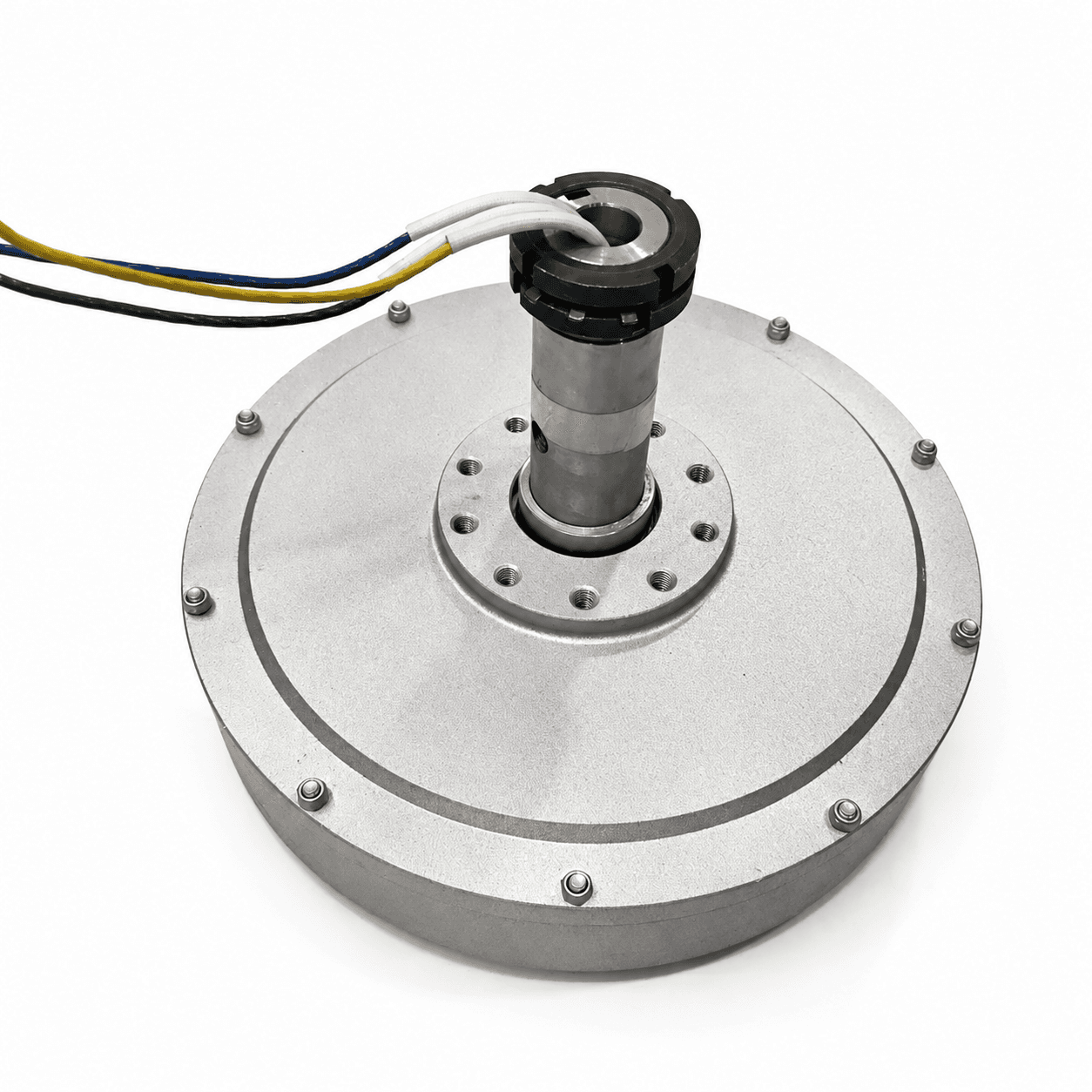
No. Supplier-reference photographs illustrate visible construction. Your quoted dimensions, materials and output curve must be confirmed for the actual program.
From constraint to a controlled brief
Bring the dimensions.
Define the evidence.
Request an engineering review ↗Prototype planning target: 3–5 weeks for suitable programs after DFM, material availability and drawing freeze. Quotation confirms feasibility, cost and schedule.