Estimate useful-current cut-in RPM and first peak conduction, accounting for rectifier diode drop, phase resistance, and commutation reactance.
Results update instantly on this device. All numeric fields are required; zero drag is allowed. Enter measured line-to-line Ke for the selected winding, branch resistance and inductance, and total cable loop resistance.
Use the actual target charging voltage, including battery state of charge, rather than its nominal label. MOSFET comparisons assume gate power is already available; cold startup may use body-diode conduction.
Preliminary sinusoidal six-pulse model: first conduction uses peak line voltage and the entered fixed device drop; useful current uses a continuous-current average approximation with overlap ≤60°. Discontinuous battery charging, magnetic/core losses, controller startup and torque-speed dynamics need bench validation. Efficiency is electrical-only. Cogging is a separate startup peak, excluded from mean running drag. Temperature is a reference; enter Ke and resistance already corrected to that temperature for the selected winding. The 25% torque screening margin is illustrative, not a stability guarantee.
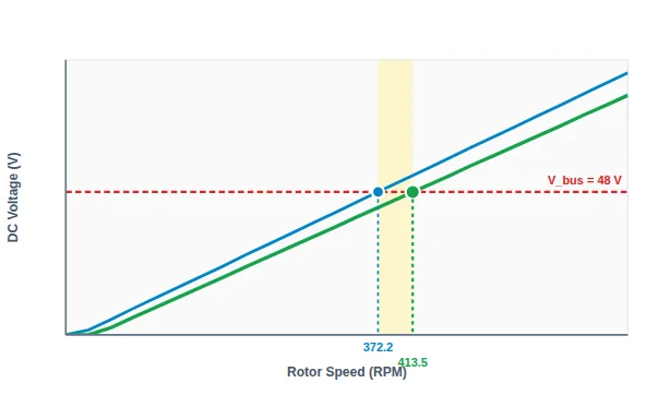
No-Load Cut-In372.2RPMUnloaded DC = V_bus
Loaded Cut-In413.5RPMDelivers 2.5 A useful current
Charging Gap (Δn)+41.4RPM+11.1% speed penalty
Total Allowance+5.05VDrop above 48V bus
✓ POSITIVE TORQUE SCREEN: Entered shaft torque exceeds this estimated requirement by at least 25%; verify the actual torque-speed curve and controller response. (Counter-Torque: 3.04 N·m vs Available: 4.2 N·m)
Generator Load-Line vs Speed (RPM)Interactive Load-Line Visualizer
No-load peak envelope (√2 × E_LL,rms − 2V_d)
Loaded Output at 2.5 A
Bus Voltage (48 V)
Charging Gap (Δn = 41.4 RPM)
414 RPM
Nearest model sample at 402 RPM: peak envelope 52 V; loaded estimate 46.53 V vs 48 V bus. Below-bus values cannot supply the target current.
Voltage Drop Allowance Breakdown at Loaded Cut-In
Drop Mechanism
Physical Equation
Value
3-Phase Rectifier Diode Drop
2 × V_d (conduction pair)
+2 V
Internal Stator Resistive Sag
I_cut × R_internal (0.9 Ω)
+2.25 V
Commutation Overlap Drop
(3/π) × ω_e × L_s × I_cut (55.1 Hz)
+0.7 V
DC Cable / Wiring Loop Drop
I_cut × R_cable_loop
+0.1 V
Total Allowance Above V_bus
Sum of drops
+5.05 V
Required Generator Line EMF
(V_bus + Allowance) / 1.3505
39.3 V_LL,rms
Impact of Rectifier Selection on Cut-In RPM (48V Bus)
Request Formal Engineering DFM Review With Current Data
Submit your preliminary cut-in speed specifications directly to the CustomAxialFlux engineering editorial team. No data is transmitted until you click submit.
How to separate open-circuit cut-in from useful loaded charging onset
In direct-drive renewable generators (wind turbines, micro-hydro, and engine auxiliary power units), cut-in speed is frequently misunderstood as the rotor speed where unloaded terminal voltage first reaches the DC battery or bus voltage. In practice, this open-circuit speed delivers zero net current into the load.
To establish a dependable engineering specification, design engineers must separate the two physical thresholds:
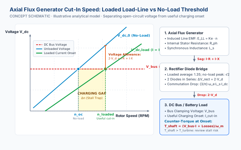
Open-Circuit Cut-In Speed (n_oc): The speed at which peak line-to-line generator back-EMF minus assumed diode drop equals the bus voltage (V_dc,0 = V_bus). At this speed, diode conduction is at the zero-current threshold. Initial pulses can be discontinuous; this differs from the average-voltage loaded model.
Useful Loaded Cut-In Speed (n_loaded): An estimated operating point where the generator delivers a defined useful charging current (e.g. 2.5 A into 48 V, producing 120 W useful output). The induced line back-EMF must exceed the bus voltage by the complete voltage allowance budget: rectifier forward drop, stator copper resistance sag, commutation reactance overlap, and cabling losses.
Calculation basis, rectifier allowance, and commutation reactance
Core equation: For a 3-phase star-connected axial flux machine rectified by a 6-pulse diode bridge, average DC terminal voltage under load is:
First peak conduction uses n_oc = (V_bus + 2V_d) / (√2 · Ke/1000). The loaded expression assumes balanced sinusoidal EMF, continuous DC current and limited commutation overlap. It is a screening approximation for battery charging, where early current pulses can be discontinuous. Ke is measured line-to-line for the selected connection; changing the connection selector does not automatically rescale Ke. For balanced, uncoupled delta branches, the model uses R_internal = 2R_branch/3 and equivalent star inductance L_branch/3. Coupling and circulating currents require a detailed machine model.
The worksheet rejects normalized commutation drop above 0.25, the simplified model’s 60° overlap boundary, and estimates above 100,000 RPM. These are worksheet scope limits, not generator speed ratings. Cogging breakaway torque is a separate startup peak, excluded from average running drag. Verify zero-speed torque and overspeed open-circuit voltage independently before choosing winding turns.
Rectifier Voltage Allowance (2·V_d): In a 3-phase full-wave bridge, current flows continuously through two series devices outside commutation overlap. The silicon preset assumes 1 V per device: its 2 V pair drop equals 16.7% of a 12 V bus or 8.3% of a 24 V bus. These are illustrative inputs, not a universal silicon voltage range; use the selected device’s current and temperature curves.
Internal Stator Resistive Sag (I_dc · R_internal): Two phases are in series in a star winding (R_internal = 2·R_ph), whereas a delta winding presents (2/3)·R_ph. Stator resistance must be evaluated at operating temperature (e.g. 65°C to 90°C), not cold 20°C ambient.
Commutation Overlap Reactance Drop ((3/π)·ω_e·L_s·I_dc): During phase commutation, current transfer between diode pairs is delayed by stator winding inductance L_s. This causes an effective DC voltage sag proportional to electrical frequency and current. In higher-speed or high-pole-count machines, commutation overlap can exceed pure copper resistance drop.
The "Cut-In Stall Trap" in direct-drive renewable generators
A frequent failure mode in custom wind and micro-hydro projects is turbine stalling upon reaching cut-in. Coreless axial flux generators can have very low cogging torque, but bearing drag and available turbine torque still constrain startup. As charging current increases, the generator demands electromagnetic counter-torque:
If the aerodynamic power of the wind turbine blades at cut-in speed cannot deliver this torque plus mechanical bearing friction, the turbine may decelerate or enter a charging hunting cycle. A single torque comparison cannot predict rotor dynamics or guarantee a stall.
To prevent cut-in stalling, specify the prime mover's available torque at the estimated loaded cut-in speed and compare the full torque-speed curves. This worksheet flags margins below an illustrative 25% screening allowance; that allowance is not a stability standard. Review current ramping or MPPT control against the actual prime mover.
Illustrative presets from the same model
The table below demonstrates three distinct application scenarios calculated with the exact same physical equations implemented in the live interactive tool. These values represent analytical sizing demonstrations for drawing review, not factory-rated catalog models.
Calculated cut-in presets · Model revision 2026-11-06
Application Scenario
DC Bus / Current
No-Load Cut-In
Loaded Cut-In
Charging Gap (Δn)
Shaft Counter-Torque
Stall Margin Verdict
Coreless Direct Drive 16P · Ke=95
48 V / 2.5 A
372.2 RPM
413.5 RPM
+41.4 RPM (+11.1%)
3.04 N·m
STABLE (+1.16 N·m)
Low-Voltage Micro-Hydro 24P · Ke=58
24 V / 3.0 A
303.6 RPM
359 RPM
+55.4 RPM (+18.3%)
2.13 N·m
STABLE (+1.67 N·m)
High-Voltage Range Extender 12P · Ke=110
350 V / 5.0 A
2250.4 RPM
2389.7 RPM
+139.3 RPM (+6.2%)
7.13 N·m
STABLE (+7.87 N·m)
Software capture, 2026-11-06: the default 48 V, 2.5 A example gives first peak conduction at 372.2 RPM and estimated loaded cut-in at 413.5 RPM. This is reproducible software output, not measured generator performance, a customer case or supplier proof.Reproduce this software capture (all 14 inputs)
Choose Reset in the live worksheet and use these values:
DC bus (V): 48
Useful current (A): 2.5
Rectifier topology: Silicon bridge
Drop per conducting device (V): 1.0
Cable loop resistance (Ω): 0.04
Line RMS Ke (V / 1000 RPM): 95
Pole pairs: 8
Phase resistance (Ω): 0.45
Phase inductance (mH): 0.85
Winding connection: Star (wye)
Temperature reference (°C): 65
Cogging breakaway peak (N·m): 0.0
Viscous drag (N·m / 1000 RPM): 0.05
Available torque at cut-in (N·m): 4.2
Conceptual engineering schematic illustrating the separation between no-load voltage threshold (n_oc) and useful loaded cut-in speed (n_loaded). Rectifier forward allowance, internal copper resistance sag, and commutation overlap create the characteristic charging gap that must be budgeted against prime-mover shaft torque.
Rectifier selection trade-offs: Silicon vs Schottky vs Active Synchronous
Selecting an appropriate rectifier topology is one of the most cost-effective methods to optimize generator cut-in speed without rewinding coils:
Standard Silicon Bridge (1.0 V per diode, 2.0 V total drop): Illustrative drop only: 2 V is 8.3% of a 24 V bus, 4.2% of 48 V, and 2.1% of 96 V. Actual drop depends on current and temperature; use a rated device curve and evaluate heatsinking.
Schottky Diode Bridge (0.45 V per diode, 0.9 V total drop): The assumed 0.9 V pair drop reduces this model’s rectifier allowance by 1.1 V relative to silicon. The resulting RPM change also depends on Ke, current and inductance. Check reverse-voltage rating, leakage and thermal derating for the chosen device.
Active Synchronous Rectifier (MOSFET ideal diode, ~0.04 V drop): The worksheet assumes 0.04 V per conducting device, 0.08 V per pair. Real drop follows current and R_ds(on); gate power, startup voltage, switching loss and controller timing are excluded. An active bridge is not a boost converter and cannot guarantee a particular cut-in RPM.
Before releasing stator winding tooling or ordering permanent magnets for an axial flux generator program, the engineering team should verify these critical design hold points:
FEA Back-EMF Validation: Verify Ke (V_LL,rms / kRPM) through 3D finite element simulation across the operating temperature range (accounting for NdFeB or SmCo remanence thermal reversible demagnetization coefficients).
Stator Phase Resistance & Temperature Rise: Validate DC resistance with dry-wound test coils and verify that operating temperature rise does not cause unacceptable copper resistance sag at cut-in.
Rectifier Thermal Dissipation: Ensure the bridge heatsink or housing mounting surface can dissipate conduction losses (P_rect = 2·V_d·I_load) under continuous low-speed high-torque operation without diode thermal runaway.
Bench Dyno Verification Plan: Conduct back-to-back dyno testing measuring shaft torque, speed, open-circuit line-to-line voltage, and rectified loaded DC voltage into a programmable electronic load set to constant voltage mode.
Frequently asked questions about generator cut-in speed
Why is open-circuit cut-in speed different from loaded cut-in speed?
Open-circuit cut-in speed is where unloaded rectified DC voltage first reaches the bus voltage, delivering zero current. Useful loaded cut-in speed requires additional speed (induced back-EMF) to overcome diode forward drop, internal stator winding resistance sag, and commutation overlap reactance.
How does rectifier diode forward voltage drop affect cut-in speed?
Two devices conduct in series. With an illustrative 1 V per silicon diode, the 2 V allowance is 8.3% of a 24 V bus or 4.2% of a 48 V bus. Actual drop depends on the device, current and temperature; use the selected device curve.
What is the 'cut-in stall trap' in direct-drive wind generators?
Low cogging does not guarantee useful charging. As current rises, electromagnetic counter-torque can exceed available blade torque and cause deceleration or charging hunting. Check the torque-speed curve and controller response; the worksheet cannot predict dynamic stability.
Can Schottky or active synchronous rectifiers lower the cut-in speed?
A lower conducting-pair drop lowers the modeled RPM requirement. The illustrative comparison uses 2 V for silicon, 0.9 V for Schottky and 0.08 V for MOSFETs. Savings depend on the bus, Ke, current and inductance. Active-controller startup and switching losses are excluded.
How does stator winding connection (Star vs Delta) affect cut-in speed?
For identical balanced coils, star gives √3 times the delta line voltage and three times its terminal resistance. Enter the measured line-to-line Ke for the selected connection; the selector does not rescale Ke. Delta branch inductance is converted to equivalent star L/3, assuming negligible mutual coupling and circulating current.
Does winding temperature increase the cut-in speed?
Hot copper resistance increases voltage sag; magnet temperature can also change Ke. This tool does not apply a temperature correction. The temperature field records a reference only: enter resistance and Ke already corrected to that temperature, based on measurements or material data.
Prepare the next engineering review
Use the live calculator above to export your project parameters, or download blank templates for manual entry and internal engineering review: