
Applications
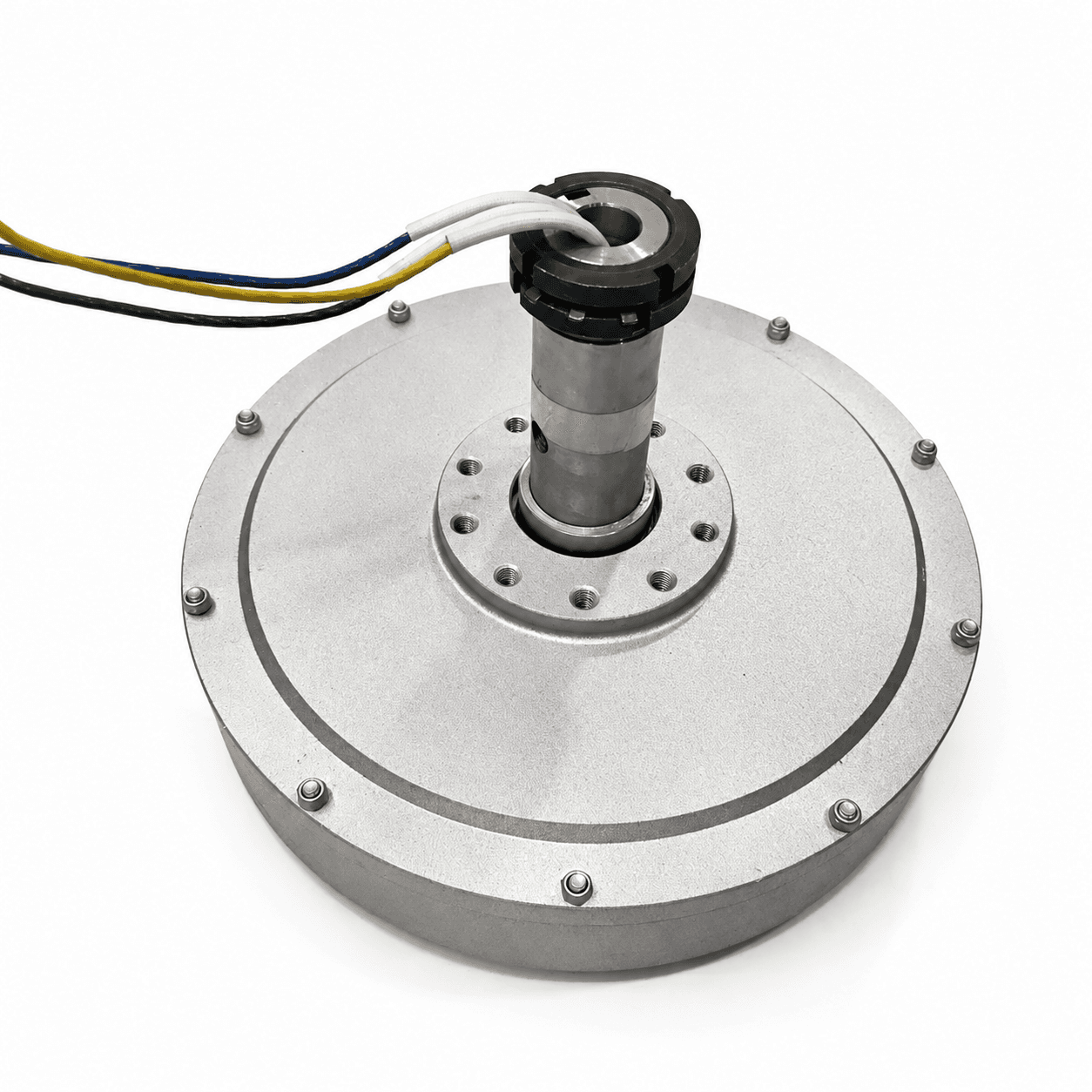
Disc generators for wind and range extenders
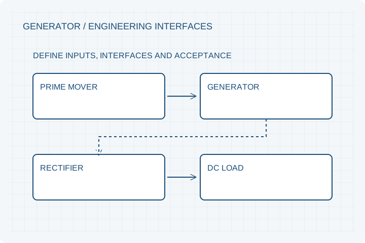
Define useful output at operating speed. A custom disc generator review connects turbine or engine torque to rectification, charging and heat removal.
Engineering editorial · Reviewed 2026-10-21
The engineering decision
Define the boundary before the build.
A wind turbine has variable speed and limited starting torque. An engine-driven range extender operates within a different speed band and needs stable electrical loading. Neither program can be specified by open-circuit voltage alone. Agree what reaches the DC load after rectification and conversion.
| Option | When it fits | Resolve before release |
|---|---|---|
| Low-speed wind PMG | Startup and output at several rotor speeds matter. | Provide the turbine torque-speed curve and desired charging threshold. |
| Engine range extender | The engine has a preferred efficiency and speed band. | Provide operating speed, vibration, coupling and load transients. |
| Coreless disc platform | Low magnetic cogging is a design priority. | Evaluate copper loss, support stiffness and loaded starting torque. |
Coreless does not mean zero resistance
Removing toothed stator iron can remove tooth-related cogging. Bearings, seals, windage and load-induced electromagnetic torque remain. Request no-load starting torque and loaded behavior as separate measurements.
Match cut-in to the charging system
A generator can produce voltage while delivering little useful current into a battery. Diode drops, converter control and bus voltage affect the onset of charging. Provide the full electrical circuit and define the threshold in terms of useful loaded output.
Separate mechanical and electrical power
Shaft power is torque multiplied by angular speed. Delivered electrical power is lower after losses. When the requested speed falls, required shaft torque rises for the same power; the rotor diameter and support system may need to change.
Prepare your RFQ
The inputs that make a useful review.
| Input | What to send | Why it matters |
|---|---|---|
| Prime mover | Torque versus speed and acceleration/start behavior | Checks available mechanical input before quoting output. |
| Electrical load | Battery range, rectifier, converter and regulation | Defines cut-in behavior and actual usable power. |
| Environment | Ambient, moisture, cooling and mounting exposure | Sets the thermal and sealing review. |
| Overspeed case | Maximum credible speed and protection strategy | Establishes the rotor retention and electrical voltage review. |
For confidential geometry, complete the NDA review before disclosure.
Continue your review
Related engineering programs
Questions before you specify
Can this replace an existing alternator?
Provide mounting dimensions, shaft/coupling loads, speed range, regulator and load details. Mechanical fit alone is insufficient.
Is a permanent magnet generator self-regulating?
No. Output depends on speed and load; rectification, regulation and protection need a defined system design.
Can you quote a Halbach rotor separately?
Yes, submit a defined magnetization pattern, dimensions, retention method and magnetic acceptance plan for review.
From constraint to a controlled brief
Bring the dimensions.
Define the evidence.
Request an engineering review ↗Prototype planning target: 3–5 weeks for suitable programs after DFM, material availability and drawing freeze. Quotation confirms feasibility, cost and schedule.