
Applications
Frameless motors for robotic joints
Fit the motor to the joint, then validate the complete axis. A shallow axial motor can preserve a central passage for wiring, hoses and sensors.
Engineering editorial · Reviewed 2026-10-21
The engineering decision
Define the boundary before the build.
A robot joint is limited by installed thickness, reflected inertia, holding duty and the surrounding structure. Peak torque alone does not describe a repeated pick-and-place cycle. Define the gearbox, bearing, brake and encoder interfaces before assuming that a frameless motor kit solves the entire joint.
| Option | When it fits | Resolve before release |
|---|---|---|
| Direct-drive joint | Low transmission backlash and a large through-bore matter. | Review required torque, rotor inertia and heat removal at low speed. |
| Geared joint | A reduction stage permits a different motor speed and torque. | Translate the load profile through ratio, efficiency and acceleration. |
| Frameless kit | The joint supplies the housing and bearings. | Assign assembly tooling, gap control and thermal contact ownership. |
Continuous holding is a thermal case
A joint can generate substantial copper loss while moving slowly or remaining stationary. Send the time spent at each holding torque and the temperature of the mounting structure. A short-duration torque target cannot be treated as a continuous rating.
Define the usable bore
A nominal rotor opening is not necessarily a usable cable passage. The final routing can be restricted by shaft walls, bearings, fasteners and connectors. Include a section drawing and the minimum service bend radius in the RFQ.
Agree acceptance before a prototype
State allowable torque ripple, test speed, instrument bandwidth and the assembled fixture. An unloaded bench result cannot automatically be applied to a robot with a gearbox, flexible housing and external cables.
Prepare your RFQ
The inputs that make a useful review.
| Input | What to send | Why it matters |
|---|---|---|
| Motion profile | Time series of torque, speed, acceleration and dwell | A peak value omits the heat accumulated while holding position. |
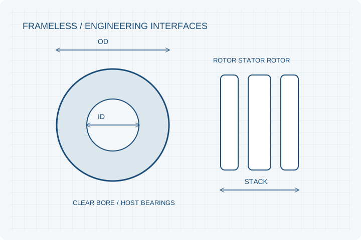
| Joint envelope | Installed OD, clear bore and full axial stack | Includes brake, encoder, bearing and cable bend allowances. |
| Control interface | Drive bus, phase-current limits and feedback format | Matches commutation and feedback to the actual controller. |
| Safety boundary | Brake, external loads and system requirements | Motor selection does not establish robot system safety compliance. |
For confidential geometry, complete the NDA review before disclosure.
Continue your review
Related engineering programs
Questions before you specify
Is the frameless kit a complete actuator?
No. Bearings, housing, brake, feedback, drive electronics and joint-level validation must be included in the system scope.
Can the bore and stack length change?
Submit both hard limits and preferred dimensions. Feasibility depends on duty, gap, structure and cooling, rather than diameter alone.
Do you supply an encoder magnet ring?
Include pole pattern, sensing distance, concentricity and sensor compatibility in the component brief. The complete sensing system needs validation.
From constraint to a controlled brief
Bring the dimensions.
Define the evidence.
Request an engineering review ↗Prototype planning target: 3–5 weeks for suitable programs after DFM, material availability and drawing freeze. Quotation confirms feasibility, cost and schedule.