
Applications
Custom drives for UAV, AGV and marine systems
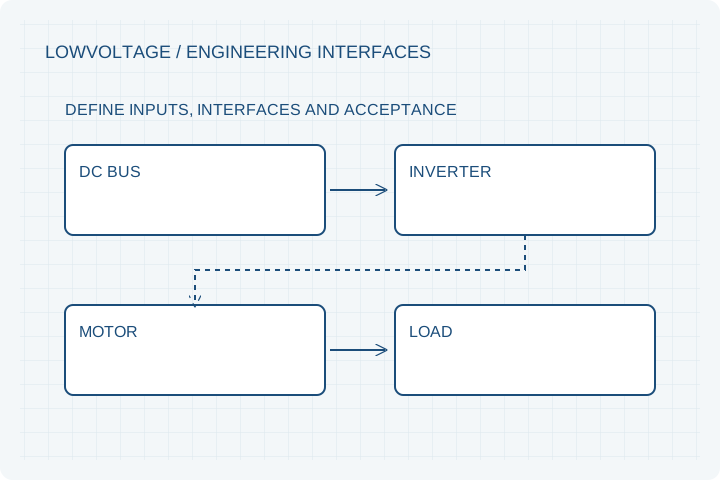
Coordinate voltage, cooling and mechanical interfaces around the vehicle. Start with the operating cycle and electrical limits of the installed system.
Engineering editorial · Reviewed 2026-10-21
The engineering decision
Define the boundary before the build.
UAV propulsion, AGV traction and marine drives share packaging constraints, but their operating cycles differ. A propeller may demand sustained high power; an AGV may repeat launch and braking events; a marine installation may introduce corrosion and a sealed cooling boundary. These programs need distinct acceptance conditions.
| Option | When it fits | Resolve before release |
|---|---|---|
| UAV propulsion | Mass and propeller operating points dominate. | Provide speed, thrust-load data, altitude and airflow conditions. |
| AGV traction or hub drive | Frequent starts, braking and packaging dominate. | Provide wheel radius, gradients, payload and regenerative limits. |
| Marine auxiliary drive | Continuous duty and the environment dominate. | Specify coolant, corrosion exposure, shaft sealing and enclosure tests. |
Low voltage means substantial current
At the same electrical input power, lower bus voltage requires more DC current. Cable cross-section, connectors, fusing and inverter capacity can become the limiting interfaces. Phase current must be specified independently because it is not interchangeable with battery current.
Treat water cooling as a defined circuit
A water jacket requires a compatible coolant, flow rate, inlet temperature, pressure drop and leak test. Salt water exposure does not establish coolant compatibility. Review the heat exchanger and isolation strategy as part of the installation.
Choose a program before a winding
Share the operating point and controller first. Winding turns, conductor geometry, speed constant and insulation then become coordinated design choices. A change in voltage alone does not guarantee the same torque-speed envelope.
Prepare your RFQ
The inputs that make a useful review.
| Input | What to send | Why it matters |
|---|---|---|
| Battery and drive | Minimum, nominal and maximum bus voltage; current limits | A nominal 48 V label does not describe the full operating range. |
| Operating cycle | Load, speed, duration and ambient conditions | Separates short peak events from thermal steady state. |
| Mechanical interface | Shaft, flange, bearings, propeller or wheel loads | External loads affect structure and installed length. |
| Cooling boundary | Airflow or coolant flow, inlet temperature and pressure | A nameplate target requires a repeatable cooling condition. |
For confidential geometry, complete the NDA review before disclosure.
Continue your review
Related engineering programs
Questions before you specify
Can a 48 V design become a 96 V design?
A winding revision may be possible, but controller compatibility, insulation, current, speed and thermal limits must be reviewed together.
Does a sealed housing establish IP67?
No. The completed assembly and its cable interfaces need the specified ingress test before an IP claim is made.
Can you help match a controller?
Include your preferred controller or request matching support. Confirm feedback, phase-current definitions, voltage range and control commissioning in the scope.
From constraint to a controlled brief
Bring the dimensions.
Define the evidence.
Request an engineering review ↗Prototype planning target: 3–5 weeks for suitable programs after DFM, material availability and drawing freeze. Quotation confirms feasibility, cost and schedule.