
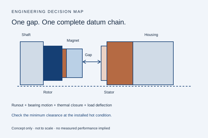
Start with the minimum running gap, not a cold drawing number
A nominal mechanical gap is the distance between the facing rotating and stationary surfaces at a stated assembly condition. It is not automatically the magnetic equivalent gap: encapsulation, nonmagnetic retention and the coreless winding region may sit in the magnetic path. Define both surfaces, reference temperature, bearing state and inspection method before comparing designs. The following review framework is an engineering planning method, not a guaranteed machining tolerance.
Draw the complete axial stack
For each active gap, trace one continuous datum chain through the locating bearing, shaft shoulder, rotor back iron, bondline, magnet/coating or retention surface, opposing stator encapsulation and stator-to-housing mount. A dual-rotor machine needs a separate check for each gap: a favorable total end-to-end dimension can still hide an off-center stator.
| Chain item | Question at drawing freeze | Evidence to request |
|---|---|---|
| Bearing / shaft reference | Which feature locates the rotor axially? What play/preload applies hot? | Bearing arrangement, fits, torque procedure and measured axial movement |
| Rotor and magnet face | Are runout, back-iron dish, coating and bondline included? | Datum-referenced assembled-face runout and thickness map |
| Stator / encapsulation | Is the finished resin or winding support the closest surface? | Post-cure flatness and assembled position, not only bare-core checks |
| Housing / mounts | Does tightening or the customer interface move the faces? | Installed condition, clamp loads and interface stiffness model |
Keep the closure budget signed and traceable
For a simple one-gap screening calculation, write g_min = g_nom − geometric closure − bearing motion − thermal closure − load deflection − reserved allowance. Here each listed term is a positive worst-case movement that closes this particular gap. Expansion may open one gap and close another. Establish the sign using the assembly geometry; do not subtract every expansion twice. Add a documented requirement for remaining clearance after the budget.
| Contribution | Illustrative closure (mm) | How it must be established on a real assembly |
|---|---|---|
| Nominal cold gap | 1.00 (starting value) | Gap map at specified reference condition |
| Assembled geometric variation | 0.12 | Tolerance stack and finished-face runout |
| Bearing axial motion | 0.08 | Operating fits, load direction and clearance/preload |
| Differential thermal movement | 0.10 | Temperature map plus constrained expansion model |
| Elastic load deflection | 0.15 | Structural analysis correlated with physical measurement |
| Reserved allowance | 0.05 | Project-defined uncertainty / contamination provision |
| Remaining screening clearance | 0.50 | 1.00 − 0.12 − 0.08 − 0.10 − 0.15 − 0.05 |
Worked scenario: a margin can disappear after integration
The numbers above are invented solely to show arithmetic; 0.50 mm is not an acceptance limit. If a customer mounting bracket adds 0.40 mm closing deflection, the same calculation leaves 0.10 mm. Neither result passes until the required residual clearance, transient conditions and measurement uncertainty are agreed. If measured runout already includes a rotor-face thickness error, remove that error from the separate stack term to avoid double counting. Statistical RSS stacking needs justified distributions and correlation; it is not a substitute for a worst-case interference check.
Hot-state stiffness is an assembly property
SKF explains that preload can improve positioning/stiffness, but its prediction depends on operating temperature and elastic behavior, including the housing. Use that general bearing guidance as a reason to verify the installed motor, not as a preload recommendation. Map magnetic attraction, external thrust, torque reaction and bearing support stiffness into the same model. Symmetry in an ideal dual-rotor magnetic model does not prove every component is free of deflection. Primary technical reference ↗
Choose a validation sequence that can reveal the failure
Agree reference conditions and stop criteria before testing. Evaluate cold assembly first, then thermal soak and transient duty, and correlate predicted movement with safe instrumentation. Any overspeed or high-voltage test requires an engineered test procedure and suitable containment; this guide supplies no test speed or energized setup instructions.
| Gate | Record | Release question |
|---|---|---|
| Cold dimensional review | Assembly serial, drawing revision, datum, angular gap map, sensor uncertainty | Are the minimum gaps and face runout within agreed limits? |
| Thermal / load correlation | Temperatures, speed/load history, housing boundary and displacement | Does the hot transient close the gap more than the model predicts? |
| Post-test inspection | Rub marks, bondline/retention condition, residual runout | Has permanent movement or contact occurred? |
| Production control | Traceable measurement method and sampling plan | Which features are controlled per unit and which by process validation? |
Make the integrator–supplier boundary explicit
For a frameless kit the customer may own bearings, housing, rotor support and final gap adjustment. The kit supplier cannot validate hot running clearance in an unknown structure. Send the installed CAD, bearing arrangement, temperature limits and external load cases with the RFQ. Ask for a responsibility matrix: who defines each allowance, who performs analysis, and who releases the assembled test. A sealed full motor still needs interface conditions; a compliant customer flange can change the result.
What this guide deliberately leaves to the project
No universal safe air gap, preload, speed limit, rotor thickness or flatness number is provided. Required stiffness depends on geometry, material, attraction forces, bearing arrangement and load cases. A simple magnet-thickness/gap flux equation omits leakage, saturation and full magnetic-path reluctance, so this page does not infer torque or feasibility from the screening margin. Request an actual drawing-controlled gap report and a correlated hot-state assessment for the proposed assembly.